Warranty, Operating instructions, Baseboard/thermostat wiring – Cadet SMART-BASE SBFT2 User Manual
Page 2: Completion of installation
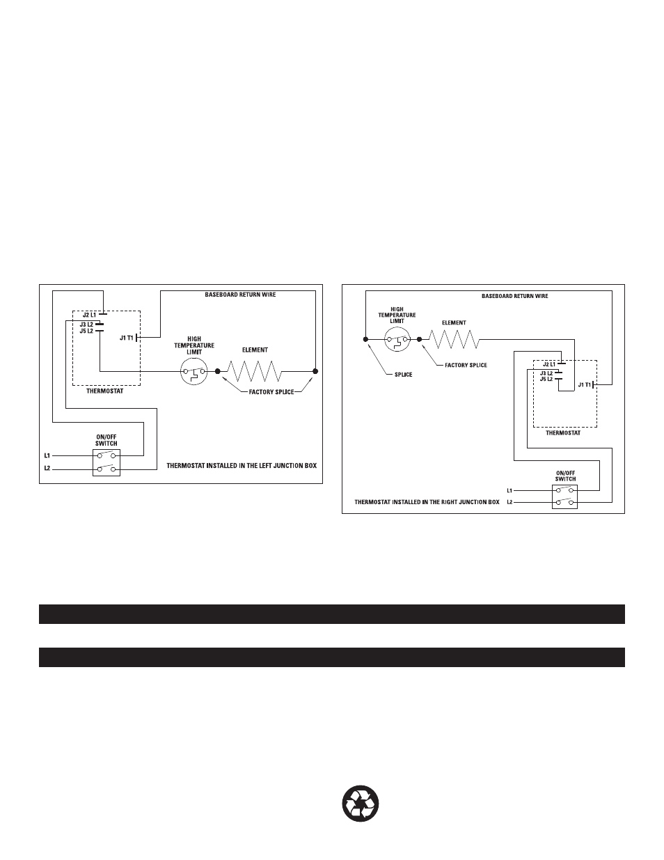
Baseboard/Thermostat Wiring
Thermostat in left junction box: (Figure A)
1. Locate and cut closed end splice of wires containing limit lead wire
and return wire (wire behind deflector). Strip 1/2” of insulation from
these two cut lead wires.
a. Join the lead wire from the limit with the lead wire from thermostat
terminal J5L2 with a connector.
b. Join the return wire (wire behind deflector) with the lead wire from
thermostat terminal J1T1 with a connector.
2. Connect the grounding lead of the power supply to the supplied
grounding screw.
3. Connect each of the remaining two power supply leads to each
lead from the thermostat rocker switch with a wire connector.
a. Be sure the panel does not interfere with the mounting of the
thermostat plate. Move panel if needed. (Using a rubber-coated
tool, or hammer handle; carefully pry upwards.)
4. Carefully push wiring back into junction box. Keep all wires away
from the Smart-Base circuit board. These wires may interfere with
the clock and thermostat’s performance. Hook upper edge of
faceplate under lip of case. Lower bottom edge of faceplate to
junction box surface and secure thermostat with mounting screw.
5. Rocker switch should be placed in the “O” (OFF) position. To finish
see the “Completion of Installation” section below.
Thermostat in right junction box: (Figure B)
1. Cut closed end splice from connection of element lead wire and
return wire (wire behind deflector). Strip 1/2” of insulation from
these two cut lead wires.
a. Join the lead wire from the element with the lead wire from
thermostat terminal J5L2 with a connector.
b. Join the return wire (wire behind deflector) with the lead wire
from thermostat terminal J1T1 with a connector.
2. Connect the grounding lead of the power supply to the supplied
grounding screw.
3. Connect each of the remaining two power supply leads to each lead
from the thermostat rocker switch with a wire connector.
a. Be sure the panel does not interfere with the mounting of the
thermostat plate. Move panel if needed. (Using a rubber-coated
tool, or hammer handle; carefully pry upwards.)
4. Carefully push wiring back into junction box. Keep all wires away
from the Smart-Base circuit board. These wires may interfere
with the clock and thermostat’s performance. Hook upper edge
of faceplate under lip of case. Lower bottom edge of faceplate to
junction box surface and secure thermostat with mounting screw.
5. Rocker switch should be placed in the “O” (OFF) position. To finish
see the “Completion of Installation” section below.
FIGURE “A” (Left Junction Box Wiring)
FIGURE “B” (Right Junction Box Wiring)
Completion of Installation
At this point, the baseboard should be securely mounted, and the SBFT2
thermostat wired and secured to the baseboard junction box. The other
junction box should have the baseboard end plate/cover secured in place.
Verify that the thermostat rocker switch is in the “O” (OFF) position
before reestablishing the electrical power at the panel for power flow
to the baseboard heater.
Refer to the General Programming Operation Guide for the operation of the
SBFT2 thermostat.
Warranty
WARRANTY: Warranties are non-transferable and apply to original consumer
only. Warranty terms are set out below.
LIMITED ONE-YEAR WARRANTY: Cadet will repair or replace any Cadet product,
including thermostats, found to be defective within one year after the date
of purchase.
THESE WARRANTIES DO NOT APPLY:
1. Damage occurs to the product through improper installation or incorrect
supply voltage;
2. Damage occurs to the product through improper maintenance, misuse,
abuse, accident, or alteration;
3. The product is serviced by anyone other than Cadet;
4. If the date of manufacture of the product cannot be determined;
5. If the product is damaged during shipping through no fault of Cadet.
6. CADET’S WARRANTY IS LIMITED TO REPAIR OR REPLACEMENT AS SET OUT
HEREIN. CADET SHALL NOT BE LIABLE FOR DAMAGES SUCH AS PROPERTY
DAMAGE OR FOR CONSEQUENTIAL DAMAGES AND/OR INCIDENTAL
EXPENSES RESULTING FROM BREACH OF THESE WRITTEN WARRANTIES
OR ANY EXPRESS OR IMPLIED WARRANTY.
7. IN THE EVENT CADET ELECTS TO REPLACE ANY PART OF YOUR CADET PRODUCT,
THE REPLACEMENT PARTS ARE SUBJECT TO THE SAME WARRANTIES AS
THE PRODUCT. THE INSTALLATION OF REPLACEMENT PARTS DOES NOT
MODIFY OR EXTEND THE UNDERLYING WARRANTIES. REPLACEMENT OR REPAIR
OF ANY CADET PRODUCT OR PART DOES NOT CREATE ANY NEW WARRANTIES.
8. These warranties give you specific legal rights, and you may also have other
rights which vary from state to state. Cadet neither assumes, nor authorizes
anyone to assume for it, any other obligation or liability in connection with its
products other than as set out herein.
If you believe your Cadet product is defective, please contact Cadet
Manufacturing Co. at 360-693-2505, during the warranty period, for instructions
on how to have the repair or replacement processed. Warranty claims made
after the warranty period has expired will be denied. Products returned
without authorization will be refused.
Parts and Service
Visit http://support.cadetco.com for information on where to obtain parts and
service.
Reduce-Reuse-Recycle
This product is made primarily of recyclable materials. You can
reduce your carbon footprint by recycling this product at the end of
its useful life. Contact your local recycling support center for further
recycling instructions.
©2009 Cadet Manufacturing Co.
Printed in U.S.A. 10/11 #720004
OPerATInG InSTrucTIOnS
See the “General Programming Operation” guide for complete operating instructions. The heater and thermostat must be properly installed before
they are used.