3 setup and operation, 1 setup of red rocket breakout box, Setup and operation – RED ROCKET BREAKOUT BOX User Manual
Page 15
DECEMBER 22, 2009
© RED.COM, INC. 2009
3-1
3
SETUP AND OPERATION
This chapter outlines connection of the RED Rocket Breakout Box to the RED Rocket board. The installa-
tion is performed in several steps:
1. Setting up and connecting the RED Rocket Breakout Box to the RED Rocket board.
2. Basic operation of the RED Rocket Breakout Box.
3.1 SETUP OF RED ROCKET BREAKOUT BOX
To set up the RED Rocket Breakout Box perform the following:
1. Place the RED Rocket Breakout Box on a firm, flat surface or install in a 19" rack-shelf near the
computer with the RED Rocket board installed.
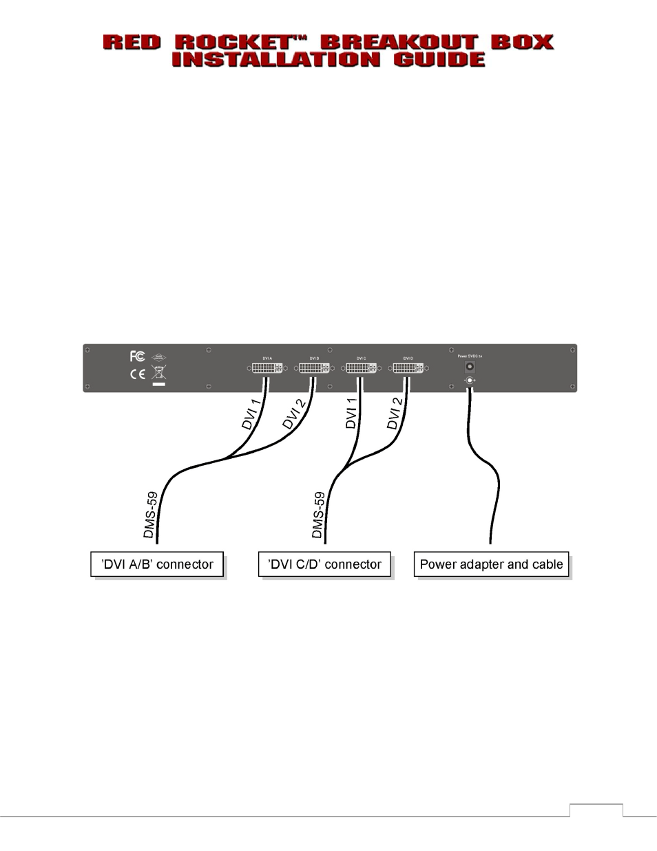
2. Connect the RED Rocket Breakout Box to the DVI A/B and DVI C/D outputs on the RED Rocket
board using the DMS-59-to-2×DVI-D connection cables (refer to 2.4 CONNECTION CABLES):
Figure 3-1: Connections of the RED Rocket Breakout Box
NOTE: In environments where quad display applications or similar are not intended, the major con-
nection ’DVI A/B’ to ’DVI A’ between board and breakout box will suffice. For specifications of the
connection cables see section A.1 TECHNICAL DATA.
3. Connect the 5V power adapter to the RED Rocket Breakout Box and plug it into a power outlet.
NOTE: When the RED Rocket Breakout Box is ON, the SDI outputs of the RED Rocket board SDI
panel, located on the rear of the RED Rocket board equipped computer, will become inoperative.
4. Connect your equipment to the appropriate connectors on front of the RED Rocket Breakout Box.
NOTE: Depending on the firmware version of the RED Rocket Breakout Box, a firmware update
may be required. Please contact RED support at
http://www.RED.com/support
.