Crestron electronic GreenLight DIN-8SW8 User Manual
Page 12
DIN Rail High-Voltage Switch
Crestron DIN-8SW8
Connectors, Controls & Indicators (Continued)
# CONNECTORS*,
CONTROLS &
INDICATORS
DESCRIPTION
4 SETUP
(LED and Button)
(1) Red LED and (1) recessed
miniature pushbutton for enabling
setup mode and touch-settable ID
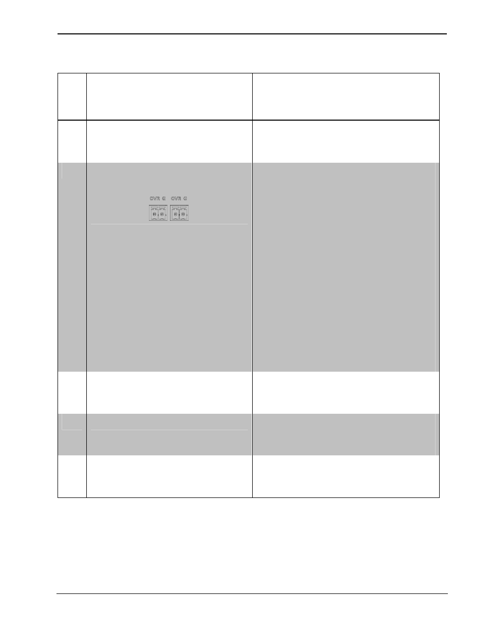
5
OVERRIDE
With LEDs and Button
(2) 2-pin 3.5 mm detachable
terminal blocks, paralleled;
Maximum wire size: 1.5 mm
2
(16 AWG)
Sensing input for external
low-voltage contact closure;
Activates Override mode when a
closure is present;
Minimum closure rating:
10 mA (per module) at 24 Volts;
(1) Red LED and (1) miniature
pushbutton for enabling Override
mode and saving override presets.
For more information, refer to
“Operation” which starts on page
20.
6
PWR
(1) Green LED, illuminates when
DC power is applied to the NET
port
7
NET
(1) Yellow LED, indicates
communication with the control
processor
8
RESET
(1) Recessed miniature
pushbutton, resets internal
processor
* Interface connectors for NET and OVERRIDE ports are provided with the unit.
8
• DIN Rail High-Voltage Switch: DIN-8SW8 Operations & Installation Guide – DOC. 6666B