Dip switch cross reference, Witch, Ross reference – PS Engineering PAC24 Installation Manual User Manual
Page 13
PS Engineering
PAC24 Series Audio Selector Panel and Intercom System
Installation and Operator’s Manual
200-240-0010
Page 2-6
Rev. 24, Dec. 2013
14 V Aircraft
28 V aircraft
Pin 18= 14 V input
Pin 18=Swap
Pin U=Swap
Pin U =28 V input
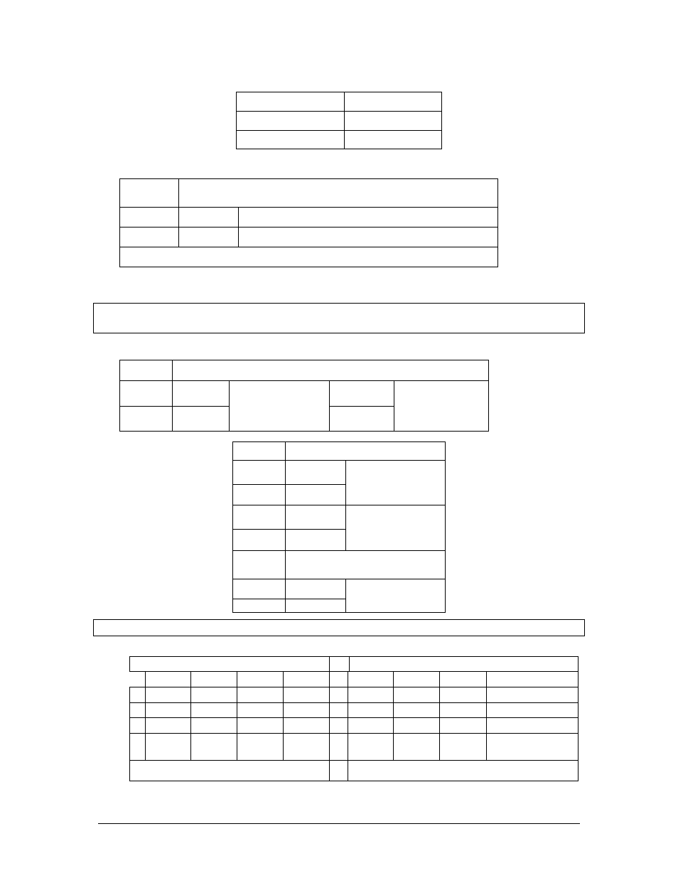
2.3.2.9
Expansion Mode / Telephone configuration (S5)
Switch
S5
1
On
Expansion Unit Present (11606 installed)
4
On
Duplex Telephone mode for Com 5
NOTE: Set both audio panels the same in a dual installation
2.3.2.10 Observer System Installation Configuration (S5)
NOTE: -0400 and -0401 units must be interfaced with other like part number units and are always dual
installations.
When the Observer versions are used (Part Number 050-240-0400, -0401) the cockpit unit is configured
as “Crew” and the Observer station is configured as “Observer.”
Switch
S5
2
ON
ON
3
OFF
Cockpit unit –
Observer Installa-
tion
ON
Observer unit –
Installation
Switch
S3
1
OFF
2
ON
Expansion In
enabled
3
OFF
4
ON
Expansion Out
enabled
Switch
S2
3
ON
4
OFF
Pass Input
In an observer unit, jumpers J4 and J5 should be configured like a copilot's unit in dual installation.
2.3.3
DIP Switch Cross reference.
Single Installation- 28 Volt Aircraft
Single panel with Expansion - 28 Volt Aircraft
SW2
SW3
SW4
SW5
SW2
SW3
SW4
SW5
1
ON
ON
OFF
OFF
1
OFF
OFF
OFF
ON
2
OFF
OFF
ON
OFF
2
ON
ON
ON
OFF
3
ON
ON
ON
OFF
3
OFF
OFF
ON
OFF
4
OFF
OFF
OFF
See
notes
4
ON
ON
OFF
See notes
J4- On/ J5- Pins 1 & 2
J4- On/ J5- Pins 1 & 2