Transmit interlock, Swap" mode, Backlighting – PS Engineering PMA7000B Installation Manual User Manual
Page 12: Ransmit, Nterlock, Acklighting, Cellular phone interconnect
PS Engineering
PMA7000B Series Audio Selector Panel and Intercom System
Installation and Operator’s Manual
200-780-0005
Page 2-5
Rev. 10, December 2012
inactive, and audio from Com 3 is presented to the headset. This allows a telephone-like audio interface.
The COM 3 input and output are compatible with aviation radios.
The COM 3 input and output are compatible with general aviation radios. However, if J2, Pin J is con-
nected to aircraft ground (either directly or through a switch), the PMA7000B is forced into Com 3-
Duplex mode. In this mode, the COM 3 input and output is compatible with many cellular telephones
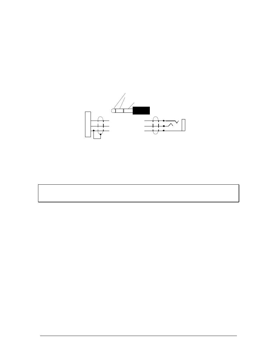
utilizing the hands-free headset interface. A 1/8" or 3/32" jack can be installed on the aircraft panel,
which is interfaced with the PMA7000B as shown below. To connect the cellular telephone to the jack
wired in to COM 3,a patch cord is required. This patch cord is available from PS Engineering under P/N
425-006-7026 (3/32" to 3/32"). A 1/8 to 3/32 adapter is P/N 425-006-2535.
3/32" Cellular Jack
COM 3 Mic Input
Com 3 Audio
Audio Lo
J
K
1
7000B
Bottom Connector
Cellular Plug (typical)
Tip= Microphone out
Ring= Speaker audio
Base=Ground
For Duplex (cell phone) operation
Pin J of top connector MUST BE GROUNDED
This is a typical interconnect
PS Engineering does not guarantee
compatability in all cases.
Cellular Phone
Interconnect
Figure 2-2 Cellular telephone interface
Unauthorized use of unapproved cellular telephone devices in aircraft is subject to FCC enforcement
action, which may include a $10,000 fine per incident. PS Engineering, Inc. does not endorse using
unapproved cellular telephone equipment in flight, and takes no responsibility for the user’s action.
2.4.8
Transmit Interlock
Some communications transceivers use a transmit-interlock system. To fully utilize the Split Mode fea-
ture, this function must be disabled. Consult that manufacturer's installation manual.
2.4.9
"Swap" Mode
When a momentary, normally open, push-button switch is connected between pin 10 on the top connector
and aircraft ground, the user can switch between Com 1 and 2 by depressing this switch without having to
turn the mic selector switch. This yoke-mounted switch eliminates the need to remove your hands from
the yoke to change transceivers. The transfer of TX indication from Com 1 to Com 2 shows that the swap
has been initiated, there is no dedicated swap indicator.
2.4.10 Backlighting
The PMA7000B has an automatic dimming of the pushbutton annunciator LEDs and marker lamps con-
trolled by a photocell. Control of the unit backlighting is through the aircraft avionics dimmer. Connect
the dimmer control line to J1 pin D for 14 volt systems, and to J1 pin F for 28 volt systems. Pin E is light
ground.
If an external dimmer control is not used, a constant low level back light illumination can be established
for nighttime viewing. Pin D or F (depending on system voltage) must be tied to power (J1, pin 20) for the
back lighting system to work. The photocell mounted in the unit face will automatically adjust the inten-
sity of the push-button annunciator LEDs.