2 scope, 3 description, Page 2 – PS Engineering PM3000 User Manual
Page 2: Page 11
Page 2
200-193-0004
Rev. 4, Aug. 2003
pilot is isolated from all others and is connected
to the aircraft radio allowing un-interrupted ra-
dio communications.
The third mode, "CREW," included in part
number 11932 (and 11934), allows the pilot and
copilot to be separated from the passengers.
The PM3000 has an automatic fail-safe intercon-
nect to the aircraft radios. If power is disrupted
to the intercom for any reason, the pilot's head-
set is connected directly to the aircraft radio al-
lowing continued radio communications.
A 2-color LED is green when power is on and
changes to red when a Push to Talk (PTT or mi-
crophone key) is pressed.
Provision for entertainment input allows the pi-
lot, copilot and passengers the option to listen to
music during flight. During intercom or aircraft
radio reception, this music will automatically
mute to allow communications without distrac-
tion. When the activity ceases, the SoftMute™
circuit gradually returns the music to the original
listening volume. By depressing the “Mute” con-
trol (located on the Squelch knob) once, it is
possible to have the music remain at a constant
level, regardless of any ICS or radio traffic.
During various phases of flight, the degree of
importance of the aircraft radio will vary. Be-
cause the "ISO" mode connects the pilot directly
to the aircraft radio, select the "ISO" mode when
the pilot must have top priority on radio trans-
missions.
Both pilot and copilot have transmit capabilities
over the radio. The PM3000 only allows the
voice of the person who presses their PTT to be
transmitted over the aircraft radio. If both pilot
and copilot press the PTT at the same time, the
copilot will override. When either pilot or co-
pilot presses PTT, all other microphones are dis-
abled. The pilot can regain priority by switching
the unit off.
Section I General Information
1.1 Introduction
The PM3000 is an FAA-TSO approved, panel
mounted, 4- to 6-place high-fidelity stereo inter-
com system (ICS). Please read this manual
completely before installation to minimize the
risk of damage to the unit and to become famil-
iar with all the features.
1.2 Scope
This manual contains installation and opera-
tional instructions for the following PS Engi-
neering unit:
Model Description Part Number
PM3000 Standard 4-place system 11931
PM3000 Crew Mode, 6-place system 11932
PM3000 4-place w/digital recorder (non-TSO) 11933
PM3000 6-place w/digital recorder (non-TSO) 11934
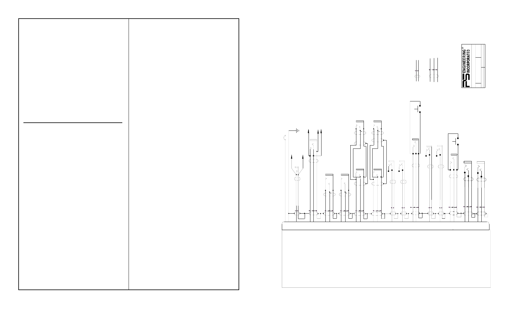
1.3 Description
The PM3000 is a 4- or 6-place (depending on
model), panel-mounted intercom with multiple
volume and VOX (voice activated squelch) cir-
cuits using unified volume and squelch controls
for the pilot, copilot and passengers.
With few controls for the pilot to use, the opera-
tion of the PM3000 is very straightforward. Yet
the unit outperforms its much more complicated
competition. Although there is only one volume
control knob, when an adjustment is made to the
volume control, all output amplifiers are being
changed simultaneously. Likewise, when the
squelch control knob is adjusted, several VOX
circuits are being changed at the same time.
Since the system is designed to use modern ste-
reo headsets, it is not necessary to balance the
volume and squelch controls at the intercom.
A mode switch allows the pilot to select differ-
ent configurations. The "ALL" mode places all
headsets on a party line. In the "ISO" mode, the
Page 11
200-193-0004
Rev. 4, Aug. 2003
Copilot Phone Audio (L)
Copilot Phone Audio (R) Copilot Phone Audio Lo
21 8
20 7
1A
12 or 28 VDC
13 1
14
PM3000 Sub-D DB-25 Male on unit
Pass 1 Mic
Pow
er In
Ground
AUX Headphone
Ja
ck
A/C
PTT
A/C Mic Audio Hi
A/C Mic Audio Lo
To Air
cr
aft Radio Mic
Audio Lo
To Air
cr
a
ft Radio Phones
Low
12 25
Air
cr
a
ft Radio PTT
To A/C Radio Mic
Audio Hi
A
u
x M
ic Ja
ck
To Air
cr
a
ft Radio
Phones
Audio Hi
P
ilo
t H
eadphone Jack
22 9
Pilot Phones (L)
Pilot Phones (R) Pilot Phones Lo
C
opi
lo
t H
eadphone Jack
P
a
ssenger
1
H
eadphone
Pass 2 & 4 Phones Audio (L) Pass 2 & 4 Phones Audio (R) Pass Phones Audio Lo
19
6
Pass 1 Mic Audio Hi Pass 1 Mic Audio Lo
15
P
ass 2 Mic
Pass 2 Mic Audio Hi Pass 2 Mic Audio Lo
2
P
ilo
t M
ic Ja
ck
C
o
p
ilo
t M
ic Ja
ck
10 23
P
ilo
t P
T
T
Pilot Mic PTT
Pilot Mic Audio Hi
Pilot Mic Audio Lo
C
o
p
ilo
t P
T
T
Copilot Mic PTT
Copilot Mic Audio Hi Mic Audio Lo
16 3
Entertainment #1 Input
24 11
Music #1 (L)
Music #1 (R)
9800 M
A
RT
E
L ROA
D
, LE
NOI
R
CI
T
Y
T
N
37922
1
1
9/27/99
2
120-131-0001
PM3000 WIRING
DIAG
RAM
SIZ
E
DO
CUM
E
N
T
NUM
B
E
R
:
TI
TL
E
:
SH
EET
O
F
EC
O
DA
T
E
:
RE
V
1
. A
ll
w
ir
e
m
u
st
c
o
n
fo
rm
t
o
M
IL
-2
2
75
9
o
r
2
7
50
0
.
M
in
u
m
u
m
2
4
g
a
g
e
s
h
ie
ld
ed
w
ir
e
.
2
.
U
se
2
-,
a
n
d
3
-,
c
on
d
u
ct
o
r
w
ith
s
h
ie
ld
a
s
in
d
ic
at
e
d
.
3
. U
se
in
su
la
tin
g
w
a
sh
e
rs
o
n
a
ll
ja
ck
s.
J
a
ck
s
m
us
t
be
e
le
ct
ric
a
lly
f
lo
a
tin
g
.
4
.
C
o
n
ne
ct
s
h
ie
ld
s
at
in
te
rc
o
m
e
n
d
o
n
ly
5
. A
U
X
h
e
a
d
p
ho
n
e
a
nd
m
ic
ro
p
h
on
e
ja
ck
s
a
re
r
eq
u
ir
e
d
.
6
. F
or
1
1
9
3
1
a
n
d
1
1
9
33
,
d
o
n
o
t
co
n
n
e
ct
p
a
ss
en
g
e
r
3
&
4
,
o
r
M
us
ic
2
in
p
ut
s.
N
O
T
E
S
:
P
a
ssenger
3
H
eadphone
P
a
ssenger
2
H
eadphone
P
a
ssenger
4
H
eadphone
P
a
ss 3
M
ic
Pass 3 Mic Audio Hi
Pass 3 Mic Audio Lo
5
P
a
ss 4
M
ic
Pass 4 Mic Audio Hi Pass 4 Mic Audio Lo
18
17 4
Music #2 (L)
Music #2 (R)
Entertainment #2 Input
2-
conduc
to
r w/
sh
ie
ld
3-
conduc
to
r w/
sh
ie
ld
SEE NOTE 6
SEE NOTE 6
SEE NOTE 6
C/
U f
or P
ubl
.
A/C Radio Phone Audio Hi A/C Radio Phone Audio Lo
Pass 1 & 3 Phone Audio (L)
Pass 1 & 3 Phone Audio (R)
Pass 1 Phone Audio Lo
PM3000 (11932, 11934) w/Crew, 6-place wiring diagram