Equipment installation procedures, Cable harness wiring, Electrical noise issues – PS Engineering 116X6 User Manual
Page 6: Quipment installation procedures, Able harness wiring, Lectrical, Oise, Ssues
PS Engineering, Inc.
IntelliPAX Expansion Unit
200-250-00085
Page
2-2
Rev. 14, Jan. 2012
2.3
Equipment installation procedures
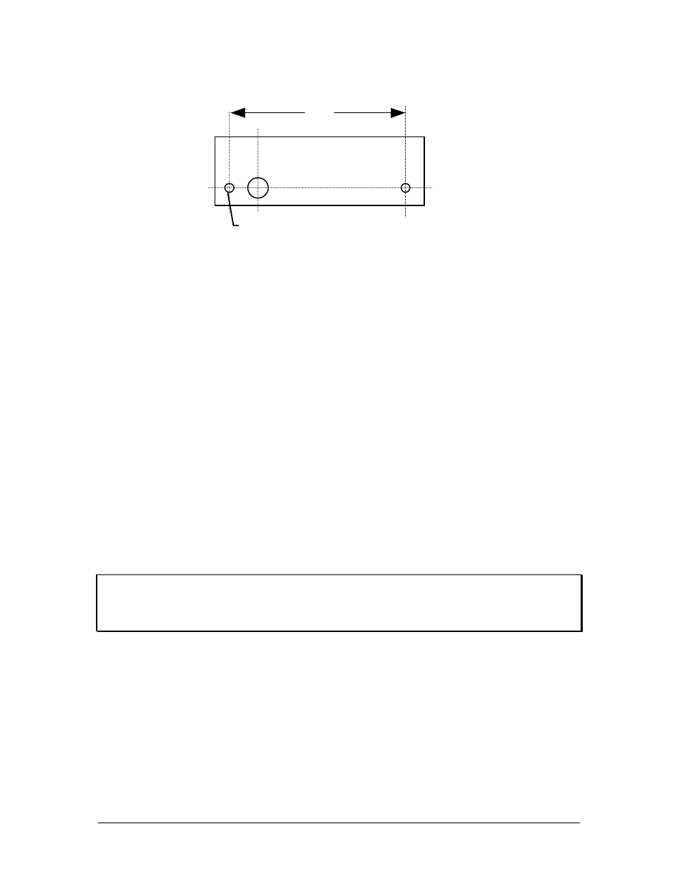
2 ea. 0.125
2.40”
NOT TO SCALE
For panel mounted installation (11606, 11616, 11626)
1. Using the template, drill three holes in the instrument panel in a location convenient to the pilot or
passengers position(s).
2. Insert the IntelliPAX from behind the instrument panel, aligning the holes for the knobs.
3. Place the aluminum faceplate over the knob shaft and secure, using the two # 4-40 round head screws
provided.
4. Install the volume knob over the volume control shafts.
Blind mounting: (11606R, 11616R, 11626R, 11606-SA 11636R)
1. Install the unit on an avionics shelf or other appropriate structure.
2. If desired, the volume can be adjusted at installation, there are two holes in the side of the unit, one
for left, and another for right channel.
3. If desired, a remote switch (not included) can be installed to override the SoftMute™ function. This
should be located convenient to the passengers.
2.4
Cable harness wiring
To complete the installation, a wire harness must be made as shown in Appendix C. PS Engineering can
make a custom-tailored wiring harness for the installer. All harnesses use Mil-spec quality components
with professional techniques, and are fully tested before shipment. Contact PS Engineering for more
information. The IntelliPAX connects to the main unit through a 4- or 5-conductor, shielded cable.
2.4.1 Electrical Noise Issues
WARNING: You must use separate shielded cables for the microphone and headphone jacks. Combining
these two wires WILL cause loud oscillations and degrade the intercom function. The oscillation is caused
by the cross-coupling between the large headphone signal and the small microphone signal. The resulting
feedback is a high-pitched squeal that varies with the volume controls.
Shielding can protect the system from radiated noise (rotating beacon, power supplies, etc.). However,
installation combinations occur where minor interference is possible. The IntelliPAX was designed in an
interference -protected chassis and has internal filter capacitors on all input lines.
Ground loop noise occurs when there are two different return paths for the same signal, such as airframe
and ground return wire. Large cyclic loads such as strobes, inverters, etc., can inject audible signals onto
the airframe return path. Follow the wiring diagram very carefully to help insure a minimum of ground
loop potential. Radiated signals can be a factor when low level mic signals are bundled with current
carrying power wires. Keep these cables separated.
Insulating washers are required on all mic and headphone jacks to isolate them from aircraft ground.