Specifications, Unpacking, Assembly – Chicago Electric 9"Angle Grinder 93179 User Manual
Page 6
Page 6
For technical questions, please call 1-800-444-3353.
SKU 93179
Specifications
Input
120 V~, 60 Hz, 15 A
Motor Speed
6500 RPM
Power Cord
82”L x 14AWG 2 prong polarized
Construction
Molded ABS Motor Housing
Cast Aluminum Gear Housing
Wheel Diameter
9” with 5/8” x 11TPI Arbor Spindle
optional 7/8” Arbor Adaptor included
Overall
Dimensions
18-1/2”L x 4-3/8”W x 5-1/2”H
unpacking
When unpacking, check to make sure that the
product is intact and undamaged.
If any parts are missing or broken, please call
Harbor Freight Tools at the number on the cover of this
manual.
Assembly
You must install the Wheel Guard (3) before using
your Angle Grinder
1.
Positioning the Wheel Guard (3)
tab
tab
press down,
then rotate
Align the tabs on the Wheel Guard (3) with the indents
in the underside of the Gear Housing (19) and press
the Guard into place as shown above.
2.
Tighten the Screw (5)
in the Guard Clamp (4)
Rotate the Wheel Guard (3) into position as shown
above.
3.
Tighten the Screw (5) in the Guard Clamp (4) to
hold the Wheel Guard (3) firmly in place.
You must install the Side Handle (24) before using
your Angle Grinder.
1.
You can install the Side Handle (24) in either the
left or right side or the top of the Gear Housing
(19).
2.
Decide which position is best for you, providing
the firmest grip while working. Pry out the Rubber
Plug (23) which is covering the threaded hole you
have selected. Place the Rubber Plug in a safe
place where you can find it again if you need it.
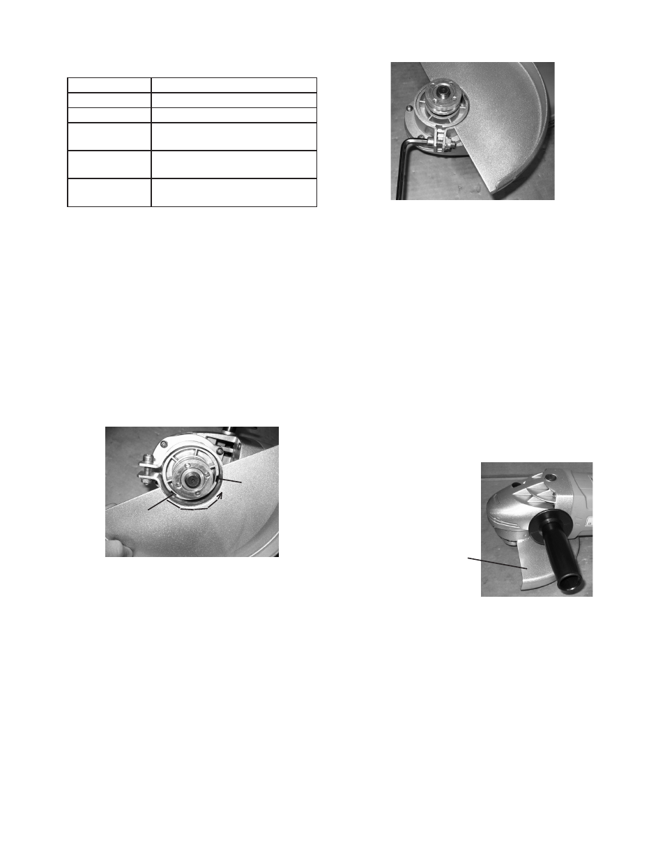
3.
Installing the Side Handle (24)
NOtE: The wheel guard
is shown in the
correct final position.
Align the threaded end of the Side Handle (24)
with the threaded hole in the Gear Housing (19)
and screw it in clockwise until it is tight.
NOtE: Periodically check to be sure the handle
remains tight. Never try to reposition the Side
Handle while the tool is running.
REV 10h