Crestron mc2e 2-series compact control system – Crestron electronic Crestron MC2E User Manual
Page 9
Crestron MC2E
2-Series Compact Control System
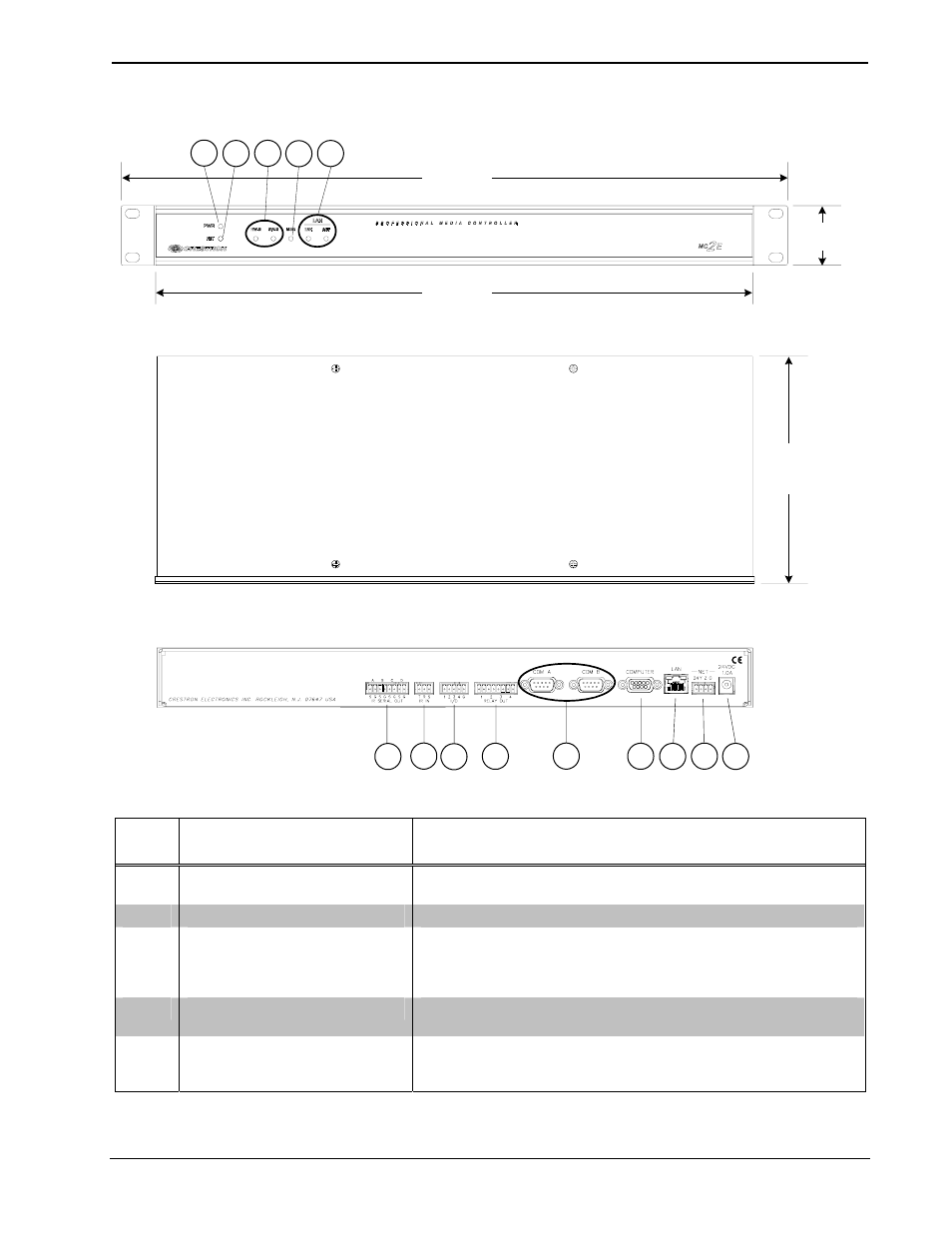
MC2E Overall Dimensions
8.50 in
(21.59 cm)
19.00 in
(48.26 cm)
17.03 in
(43.25 cm)
1.70 in
(4.32 cm)
1
2
3
4
5
14
13
12
11
10
9
8
7
6
Connectors, Controls & Indicators
#
CONNECTORS
1
,
CONTROLS & INDICATORS
DESCRIPTION
1 PWR
LED
Indicates 24 Volts DC power supplied from Cresnet control network
or external power supply.
2
NET LED
Indicates communication with Cresnet System.
3 RESET
BUTTONS
HW-R - Initiates system hardware reset.
SR-R - Pressing this in combination with HW-R button performs a
system restart without loading the program. Pressing it alone while
the system is running restarts the program.
4
MSG LED
2
Illuminates when a message is present in the message log. To view
the contents of the message log, use Crestron Toolbox™.
5 LAN
LEDs
LNK – Indicates when there is a connection to the rear panel LAN
port.
ACT – Indicates communication (activity) at the rear panel LAN port.
(Continued on following page)
Operations Guide – DOC. 6142A
2-Series Compact Control System: MC2E
• 5