Series compact control system crestron mc2e – Crestron electronic Crestron MC2E User Manual
Page 10
2-Series Compact Control System
Crestron MC2E
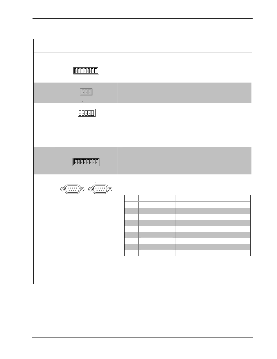
Connectors, Controls & Indicators (Continued)
#
CONNECTORS
1
,
CONTROLS & INDICATORS
DESCRIPTION
6
INFRARED-SERIAL
OUTPUT (A – D)
3, 4
A B C D
S G S G S G S G
IR SERIAL OUT
(4) 2-pin 3.5 mm detachable terminal blocks IR/Serial output ports;
IR output up to 1.2 MHz;
1-way serial TTL/RS-232 (0-5 Volts) up to 115.2k baud;
Individual signal generator per port, allowing simultaneous firing of
all ports.
7
IR IN
IR IN
T R S
(1) 3-pin 3.5 mm detachable terminal block;
For connection of the CNXRMIRD IR Receiver (sold separately);
Allows IR wireless control from Crestron or third-party universal
remotes using RC-5 IR commands.
8
I/O (1 – 4)
5, 6
I/O
1 2 3 4 G
(1) 5-pin 3.5 mm detachable terminal block comprising (4) digital
input/output or analog input ports (referenced to GND);
Digital Input: Rated for 0-24 Volts DC, input impedance 20 kΩ, logic
threshold 1.24 Volts DC;
Digital Output; 250 mA sync from maximum 24 Volts DC, catch
diodes for use with “real world” loads;
Analog Input: Rated for 0-10 Volts DC, protected to 24 Volts DC
maximum, input impedance 20 kΩ;
Programmable 5 Volts, 2 kΩ pull-up resistor per pin.
9
RELAY OUTPUT
(1 – 4)
1 2 3 4
RELAY OUT
(1) 8-pin 3.5 mm detachable terminal block comprising (4) normally
open, isolated relays;
Rated 1 Amp, 30 Volts AC/DC,
MOV arc suppression across contacts.
10
COM (A – B)
7, 8, 9
COM B
COM A
(2) DB9 male, bidirectional RS-232/422/485 ports;
Up to 115.2k baud;
Hardware and software handshaking support;
All ports support C2N-NPA8 Network Poll Accelerator
10
.
PIN DIRECTION
DESCRIPTION
1*
To MC2E
(RXD-) RS-422 Receive Data (Idles low)
2
To MC2E
(RXD) RS-232 Received Data
3
From MC2E
(TXD) RS-232 Transmitted Data
4
From MC2E
(TXD+) RS-422 Transmit Data (Idles high)
5
Common
RS-232 and RS-422 Signal Common
6
To MC2E
(RXD+) RS-422 Receive Data (Idles high)
7
From MC2E
(RTS) RS-232 Request to Send
8
To MC2E
(CTS) RS-232 Clear to Send
9
From MC2E
(TXD-) RS-422 Transmit Data (Idles low)
* RS-422 transmit and receive are balanced signals requiring two lines plus
a ground in each direction. RXD+ and TXD+ should idle high (going low at
start of data transmission). RXD- and TXD- should idle low (going high at
start of data transmission). If necessary, RXD+/RXD- and TXD+/TXD- may
be swapped to maintain correct signal levels.
(Continued on following page)
6
• 2-Series Compact Control System: MC2E
Operations Guide – DOC. 6142A