Compex Systems Professional Portable Mixing Console SONOSAX SX-S User Manual
Page 17
To make the external slate Mic operational you will need to solder in R-7=15kOhms (R-5=49.9) and C-11=22pF
remove R-10 on the extension module operator board. Unsolder the internal mic on Connectors J-10 & J-11.
Then connect J-12 to the Bantam jack. Make sure that Jumper 2 is in position 2,3.
NOTE: The internal Slate Mic is deactivated by this procedure.
SX-S10 only: Remove the unused wire on the Bantam connector.
7.4 Y Cables for Boom Operator with tbk mic transmitter.
Click here for DIAGRAMof "Y" Cable
Internal connections of the Boom-Box (022260)
Click here for BOOM BOX Wiring Diagram
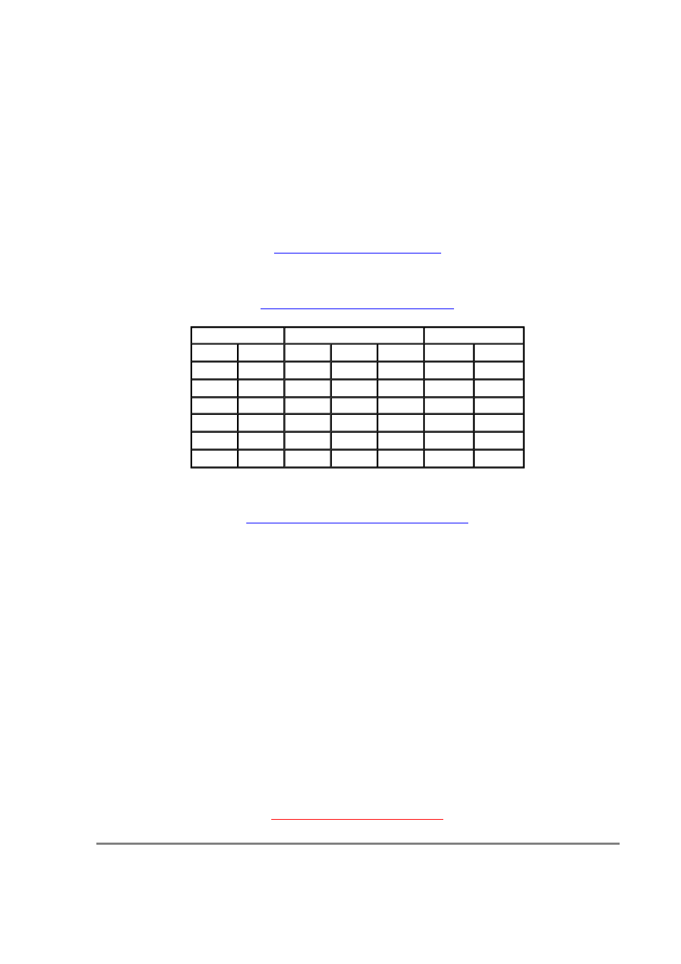
922110 External cable between SX-S extension module and SX-S extension box
Click here for MALE and FEMALE Socket Wiring
RETURN TO TABLE OF CONTENTS
860162
860179
860141
Pin No
Cable
Pin No
Cable
Pin
1
White
Tip
White
2
White
Ring
Red
1
GND
Black
3
White
GND
GND
3
White
Black
4
2
Red
Black
5
6
Pin No
Pair No
Cable
Designation
12
4
Shield
GND
11
4
White
-12V
10
4
Yellow
+12V
9
3
Orange
Guest
8
3
White
Roll
7
3
Shield
12V micro
6
2
Red
Right from Ext. Box
5
2
White
Left from Ext. Box
4
2
Shield
GND from Ext. Box
3
1
Brown
Right to Ext. Box
2
1
White
Left to Ext. Box
1
1
Shield
GND to Ext. Box
Seite 17 von 22
SONOSAX SX/S USER MANUAL
26.08.2004
file://D:\Z_Library\Webcopy\sonosax\SXS\sxsume.html