O.S. Engines GT60 User Manual
Page 2
238
2210-12 238-10
248-10
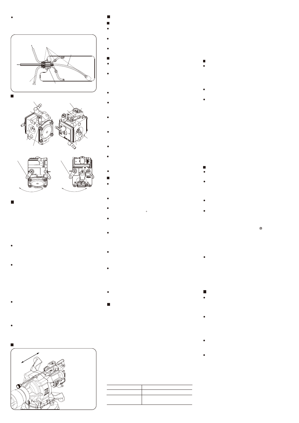
Fuel Inlet
CARBURETOR PARTS NAME
High Speed
Needle
Slow Speed Needle
Throttle Valve Lever
Choke Valve
Lever
Throttle Valve Lever
Retaining Screw
Choke Valve Lever
Retaining Screw
CARBURETOR LINKAGE
NOTE
Before connecting the throttle linkage, make sure
that the throttle valve lever does not interfere with
the bulkhead or mount of the model when it is fully
closed and opened.
In order to obtain suitable idling, connect the throttle
linkage so that the throttle valve lever may be
located at 2 to 3 degrees opened position from fully
closed position when the throttle stick on the
transmitter is fully pulled down, and the throttle valve
may be fully closed when the throttle stick as well as
the rim lever on the transmitter are fully pulled down
or engine cut-off mixing is operated.
Connect the linkage so that the throttle valve is fully
opened when the throttle stick on the transmitter is
fully advanced. (Adjust the movement so that the
pushrod does not bind when the throttle valve is fully
closed and fully opened.)
Connect the linkage so that the servo arm and
pushrod, and throttle valve lever make a right angle
when the throttle stick on the transmitter is placed at
mid position to avoid differential action.
Choke valve rod Linkage
Connect the linkage
as illustrated.
NOTE
Linkage parts are
not supplied.
Consumption current is 600mA/6,000rpm. User a
power source of more than 1000mAh capacity.
The ignition module is set not to operate below
120rpm for safety.
The voltage of power source is 4.8~7.6V (rated).
(Ni-Cd, Ni-MH 4~6 cells, Li-Po, Li-Fe 2 cells)
IGNITION MODULE
Major specifications
Installation
Install the ignition module taking sufficient
anti-vibration measures.
Install the ignition module at least 100mm away
from the engine and in a place where there is airflow
so that engine exhaust heat and radiation heat do
not affect it's operation.
Do not share the power source with receiver and
use a separate power source.
Equip an ON/OFF switch between the ignition
module and its power source and install it in a place
where can be operated from outside the model.
Install the ignition module and its power source as
far as possible away from the servos and receiver
power source.
Connect the sensor leads of the igniter module
(while, red, black three parallel wires) to the sensor
leads from the engine.
Connect the battery leads of the igniter module (red,
black two parallel wires) to the power source.
Make sure the jackets of high tension cord does not
touch the engine and cowl to avoid accidental short
circuit.
Install he plug cap on the plug securely.
Precautions
Do not disassemble the ignition module and plug
cap. (The ignition module is irreparable. Replace it
when necessary.)
Be careful not to mount the ignition module so that it
can be hit by water, gasoline or exhaust.
Avoid using the engine when the external
temperature is over 40 C.
Do not move the rpm sensor as it is placed at it's
optimum position, otherwise the engine will not run
properly.
Do not pull on the high tension cord to remove the
plug cap, or the wire will break. Be sure to hold the
plug cap to remove it. Be careful not to damage
your fingers while removing it.
Do not connect nor disconnect the rpm sensor with
the ignition module on, or there is a possibility it will
fire and the engine start.
Check the ignition module for spark when installing
the plug cap on the plug and be careful about
getting a shock. Make sure there is no flammable
material or gasoline vapors near by that could
ignite.
Do not turn the propeller with the ignition module
on, or there is a possibility the engine will start.
PROPELLER
The choice of propeller depends on the design and
weight of the aircraft and on the type of flying in which
you will be engaged. Determine the best size and type
after practical experimentation. As s starting point,
refer to the props listed in the table shown below.
Slightly larger, or even slightly smaller props than those
shown in the table may be used, but remember that
propeller noise will increase if blade tip velocity is
raised due to high rpm or if a larger diameter/lower
pitch prop is used. Be well aware propeller rotating arc
is very large due to a large propeller used with this
engine. Carry out the needle adjustments only after
stopping the engine. Do not allow your face or hands to
come close to the rotating prop.
Type
Size (DxP)
Running-in
Acro/Scale
Warning:
Make sure that the propeller is well balanced.
An unbalanced propeller and/or spinner can cause
serious vibration which may weaken parts of the
airframe or affect the safety of the radio-control
system. Do not use any propeller which has
become split, cracked or nicked even very slightly,
or received strong impact even if no apparent
damage is visible.
PROPELLER & SPINNER ATTACHMENT
Since the GT60 is intended to be started with an
electric starter, the addition of a spinner assembly for
centering the starter sleeve is desirable. Special
propeller locknut sets are available for use with
spinners. Use a good quality well balanced spinner,
enclosing the propeller boss. Make sure that it is of
precision-made and sturdy construction so that the
spinner shell cannot loosen when the starter is used.
Make sure the spinner notches do not interfere the
propeller. If they do, cut the notches to clear.
MIXING OF OIL
Use regular gasoline. (No need to use high octane
gasoline.)
Alcohol based glow fuel cannot be used in this
engine. Not only will the engine not work properly
but the internal carburetor plastic parts will be
damaged.
Use high quality commercially available 2 stroke
engine oil.
Follow the oil manufacturer’s recommendations
concerning the mixture ratio of gasoline and oil. If
there is no recommendation, mix with a 30:1 ratio.
We have checked and approved the following oil
mixture ratio. KLOTZ ModelLube (50:1), COSMO
Cosmo Terra 2 cycle (50:1), RED LINE Two-Stroke
Racing Oil (40:1). (This does not mean we
guarantee the quality of these oils.)
Follow the instructions in the running-in section
concerning the mixture for running-in.
With a gasoline engine, passages in the carburetor
are narrower than that of a glow engine, and
therefore very sensitive against foreign matter such
as dust. It is suggested to use optional accessory
Super Filter L (Code No. 72403050) when filling a
tank in the model from a container used for
transportation or storing.
When changing the throttle valve lever and choke
valve lever direction, loosen and tighten each
retaining screw placing each lever at mid position.
(If the throttle valve lever retaining screw is
loosened or tightened with the throttle valve fully
opened or closed, excessive force will be applied,
which will results in breaking the lever.)
(ON)
(OFF)
Throttle Valve
Lever
Choke Valve
Lever
Choke
Throttle
Open
Close
(OFF)
(ON)
Choke
Open
Close
Open
Close
Be sure to install an in-line fuel filter between the
tank and carburetor to prevent foreign matter in the
tank from entering the carburetor. Clean the filter
periodically.
Use a wooden or a carbon fiber propeller.
Do not use a nylon propeller.
If the supplied retaining screws are too long due to a
thinner prop hub or too short due to a thicker prop
hub (cannot be screwed into the drive hub by more
than 10mm), Use suitable length strong steel hex
socket head cap screws.
Install the propeller before the first flight of the day
and remove it after the day’s flight.
Make a habit of always checking the tightness of
propeller retaining screws making sure they are free
of, damage or rust before starting the engine.
Replace the propeller periodically (every 50 flights)
even if it looks as ifs nothing is wrong.
Use a fuel with increased oil content and set the
needle a little on the rich side. Too rich a needle
setting may cause misfiring or erratic running due to
fouling of the plug.
Use a 25:1 fuel/oil mixture if the particular brand of
oil states 50:1 mix. Use a 20:1 fuel/oil mixture if the
particular brand of oil states 30:1 mix. Set only the
high speed needle 200 below maximum rpm. The
low speed needle need not be richened.
No need to carry out running-in on a bench nor with
the model fixed. Just fly the model with the above
mentioned fuel and needle setting.
A total of 10 flights (5~6 litters fuel) are required.
Avoid prolonged full throttle running at initial stage,
and gradually extend the full throttle running time.
RUNNING-IN / STARTING
WARNING:
When ground running the engine, avoid dusty or
sandy locations. If dust or grit is drawn into the
engine, this can have a ruinous effect, drastically
shortening engine life in a matter of minutes.
Throttle Valve
Choke Valve
Be sure to use a gasoline
resistant fuel tank cap.
Be sure to equip
air vent pipe.
Be sure to replace tubing
inside periodically.
tubing for
re-fuelling
Be sure to use fuel line keepers of
stainless wire, etc. to prevent tubing
from coming off.
To carburetor
fuel inlet