Led display, Fig.1, Ch3 aux – O.S. Engines FS-91 II FI User Manual
Page 8
8
F S
SERIES
MADE IN JAPAN
CH3
AUX
(7) L.E.D.(Display of green and red)
It flashes or changes color when setting and cheking limit, and adjusting injection trim. It flashes with the color of
the injection trim when the engine is running.
LED Display
When the engine
is not running
When the engine
is running
Transmitter Operation
LED Status
Red lights
Green lights
Flashes
(color depends or the dial position)
Red flashes
Green flashes
Turn the dial right to reduce injection volume.
Turn the dial right to reduce injection volume.
Turn the dial left to increde injection volume.
Turn the dial left to increde injection volume.
Limit position
Turning direction of dial shows the standard setting direction.
Dial position shows plus (green - rich) or minus (red - lean) from the zero position (basic injection volume.)
(8) Integrated Buzzer
Buzzer sounds when setting Limit, dial is set nnetral a error happens.
Buzzer notes and status
Notes
Status
Nil
One note (Pi)
Two successive notes (PiPi)
Repeated one note (Pi...Pi...)
Repeated two successive notes (PiPi...PiPi...)
Repeated three successive notes (PiPiPi...PiPiPi...)
Normal
Limit at Low is set
Dial neutral
Limit at High is set
Temperature Sensor is disconnected
Error on setting Limit
Battery voltage falls down (below 3.8v)
mark shows alarm for error.
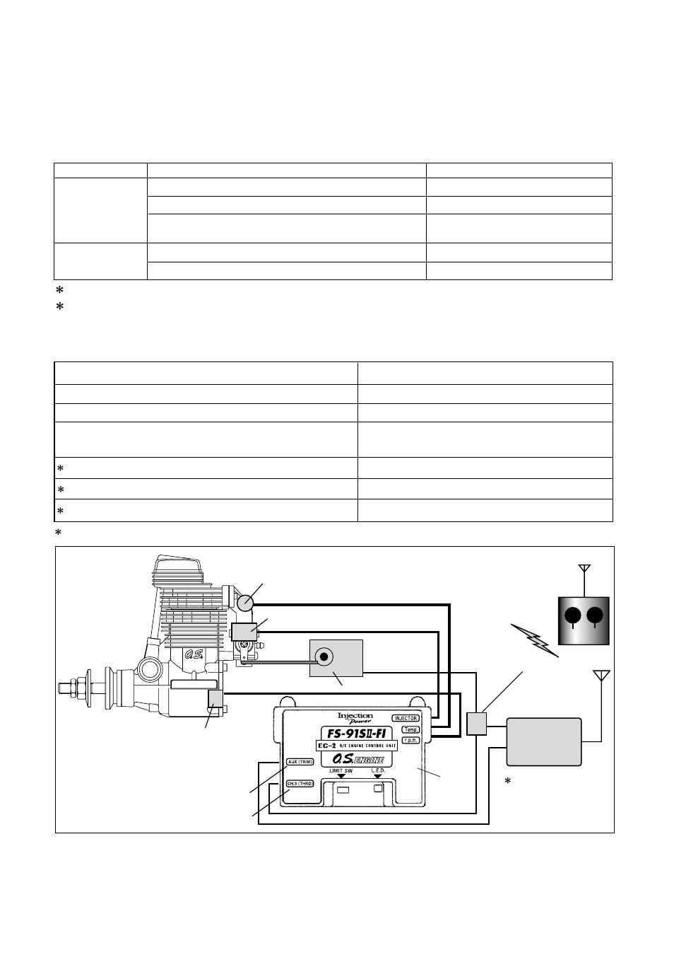
AUX
Temperature Sensor
Throttle Servo
Branched Cord
Transmitter
Receiver
Spare Channel
Injector
Rotation Sensor
Fig.1
Throttle Channel
EC-2