1 introduction, 1 vt software version, 2 list of parts – NORAC 54VT-PRO-PT01 User Manual
Page 4: 3 alternate cabling
2
1 Introduction
The Case AFS Pro 300, 600, 700 & INTELLIVIEW II, III, IV Display Kit Manual is intended to be
used in conjunction with the UC5 Spray Height Control Installation Manual. This manual
provides instructions to interface the UC5 Control Module to the Case AFS Pro 300, 600, 700
or INTELLIVIEW II, III, IV Display. For installation of the rest of the UC5 Spray Height Control
System please refer to the sprayer specific manual provided with the kit.
1.1 VT Software Version
Before connecting the UC5 to the Case AFS Pro 300, 600 or 700, ensure that the latest VT
software is installed. The VT software must be Version 25 or newer.
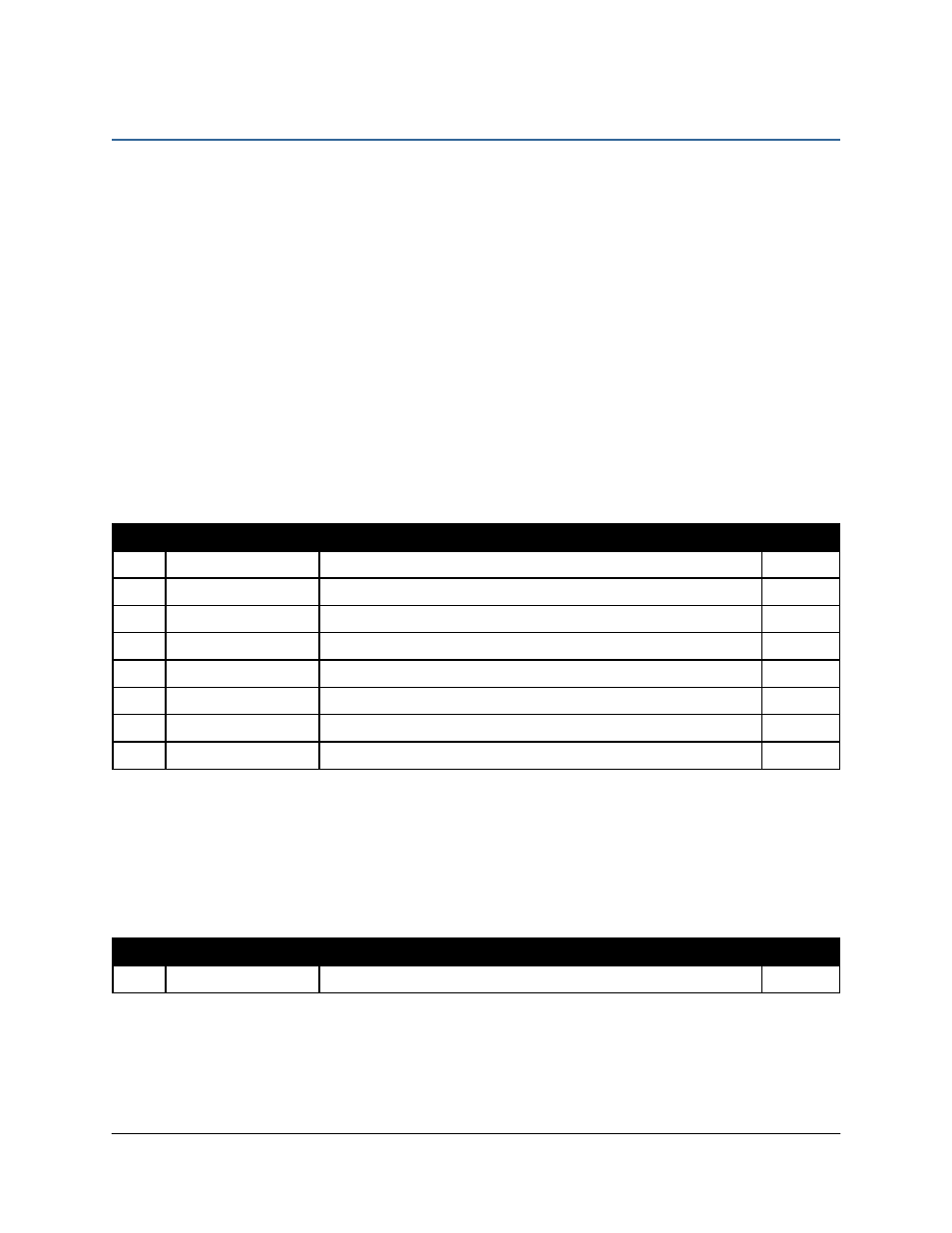
1.2 List of Parts
Item
Part Number
Name
Quantity
C25
44602-01
BOX SWITCH UC4 REMOTE HAND CONTROL VER.1 RMR
1
C26
43240-26
CABLE UC5 INTERFACE SWITCH BOX
1
C30
43250-06
CABLE UC5 BATTERY PIGTAIL FUSED
1
C40
43260-08
CABLE UC5 INTERFACE CAN BUS 4 PIN DT
1
C41
43220-03
CABLE UC5 NETWORK 14 AWG 3M
1
E12
43764
UC5 NETWORK COUPLER 2-WAY
1
M01
UC5-BC-MANUAL-VT
MANUAL UC5 OPERATORS - ECHO/VT
1
M04
54VT-PRO-PT01-INST
MANUAL UC5 DISPLAY KIT CASE AFS PRO 300, 600, 700 & INTELLIVIEW II, III, IV (CASE & NH
ISOBUS READY)
1
1.3 Alternate Cabling
Some tractors may require a different C40 cable depending on the connectors used for the
ISOBUS. Please refer to the table below for ordering alternate cabling from NORAC.
Item
Part Number
Name
Quantity
C40
43260-09
CABLE UC5 INTERFACE CAN BUS 6 PIN METRI-PACK 150
1