3 hydraulic plumbing – NORAC UC4+BC+SC1 User Manual
Page 22
19
4.6.3 Hydraulic Plumbing
WARNING!
From this point in the installation the
booms will be inoperative until the
electronics are fully installed.
1. After the NORAC valves are mounted, the
hydraulic hoses and fittings can be plumbed.
The plumbing for the hydraulic circuit is
shown schematically in Figure 3.
2. The “B” ports leading from the NORAC
valve block are the “raise” lines, and must be
connected to the boom raise cylinders via
the existing lines and the “T” fittings (F04).
The “T” fittings are inserted into the existing
Spra-Coupe hydraulic circuit to allow the
NORAC Valve block to control the
cylinders in parallel with the existing system.
3. NORAC supplies four new hydraulic hoses
(H03) to run to the “T” fittings (FO4).
4. Route the lines from the NORAC valve
block to the “T” fitting which is inserted at
the junction of the steel hydraulic line and
the hose of the Spra-Coupe circuit.
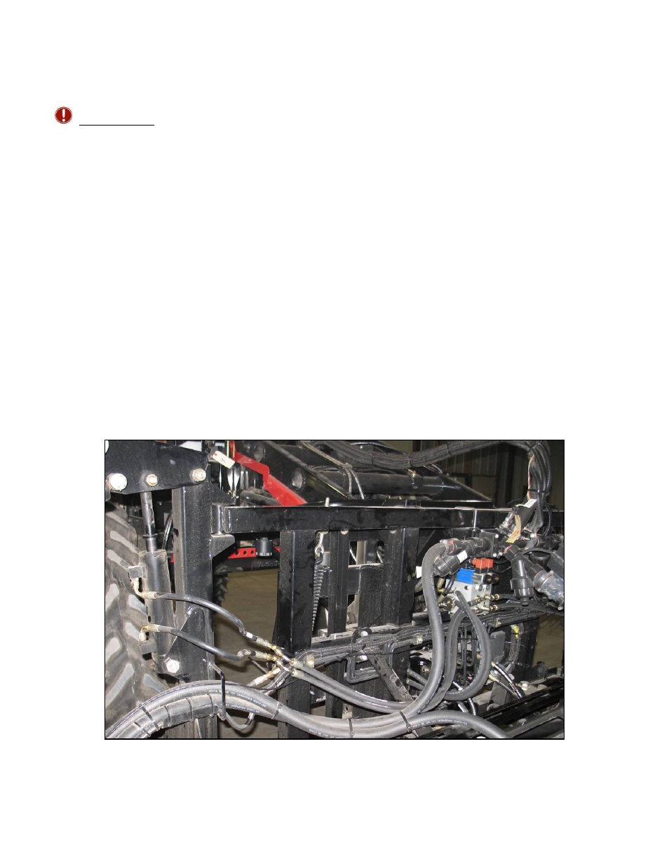
5. Remove the existing Spra-Coupe Pressure
and Tank lines from the Spra-Coupe valve
block and fit them to the NORAC Pressure
(P) and Tank (T) ports, using the “T” fitting
(F02). Attach the two hoses (H02) to F02.
6. Use the 90 degree 6MJ 6FJX90 fittings (F03)
to attach the other end of H02 to the Spra-
Coupe Pressure and Tank ports.
Figure 24: Boom Cylinder Plumbing