NORAC UC4+BC+HD1 User Manual
Page 25
22
11. Connect the 4-pin AMP plug on the
sensor trunk cable (C01) to the 4-pin
AMP Receptacle on C06.
12. Route C01 and C04 to the rear of the
sprayer following existing wiring and
hoses.
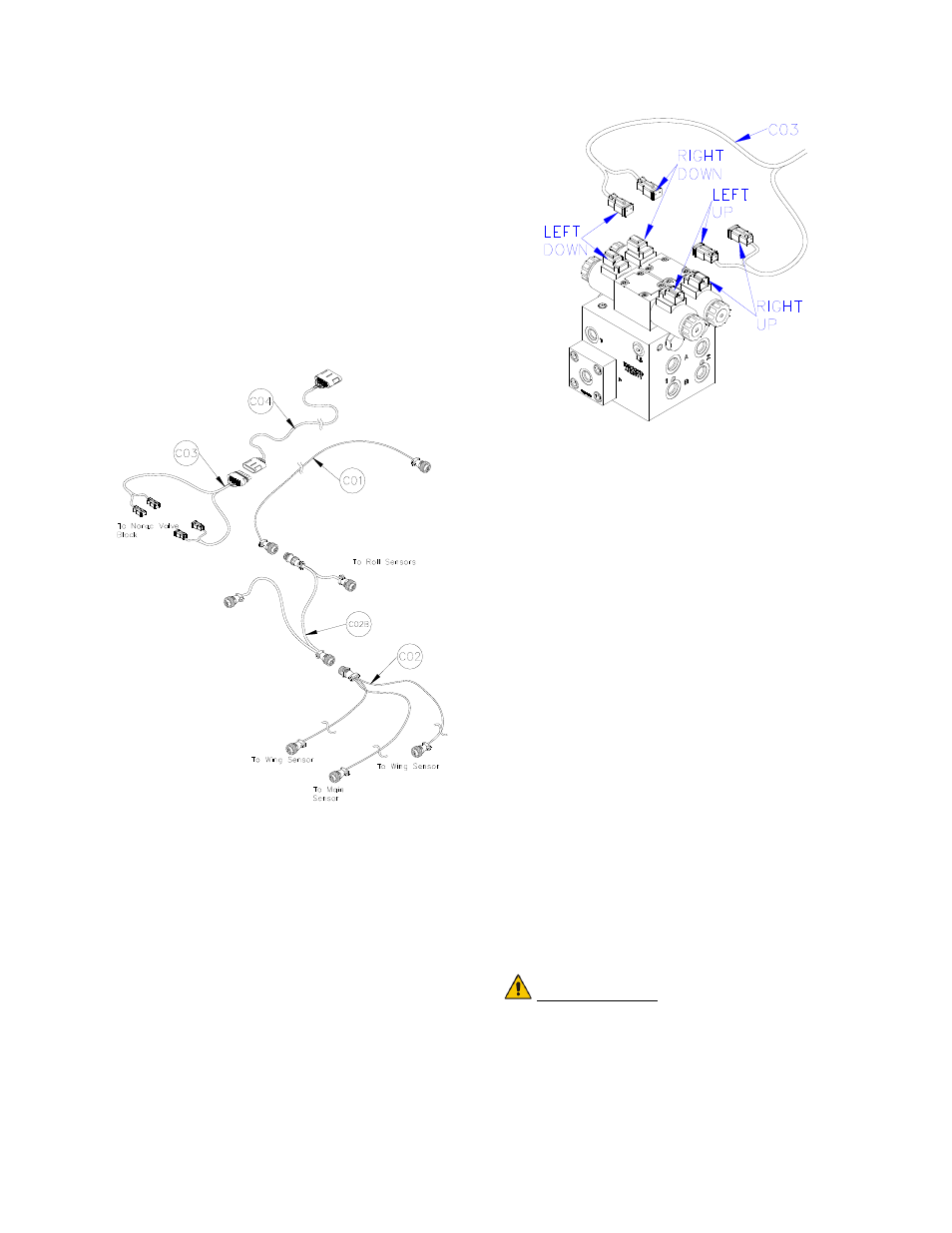
13. Connect the 6-pin Tower on the UC4+
valve cable (C03) to C04 at the rear of
the sprayer (Figure 26).
Figure 26: Cable Configurations: C01,
C02, C02B, C03 and C04
14. The connectors on the valve cable
(C03) are marked RIGHT UP, LEFT
UP, RIGHT DOWN and LEFT
DOWN. Cables labeled with UP go
on the same side as the hydraulic hoses.
Figure 27: Valve Cable Connections
15. Connect the CAN Node cable (C02B)
to the 4-pin AMP plug on C01 (Figure
26).
16. Route the CAN Node cable (C02B) to
the roll sensors which are installed in
Section 4.5. Follow existing cables
and/or hydraulic lines.
17. Connect the 4-pin AMP connectors to
the roll sensors.
18. Connect the sensor branch cable (C02)
to the 4-pin AMP plug on C02B
(Figure 26).
19. Route the sensor branch cable (C02) to
the wing and main sensors and connect
to the sensors. Follow existing cables
and/or hydraulic lines along the boom.
20. Cable-tie the installed cables every 12
inches.
IMPORTANT:
Provide enough slack in all cables to
account for the movement of the
main section, parallel lift, and
FOLDING boom movement.