NORAC UC4.5-BC-MS1 User Manual
Page 19
16
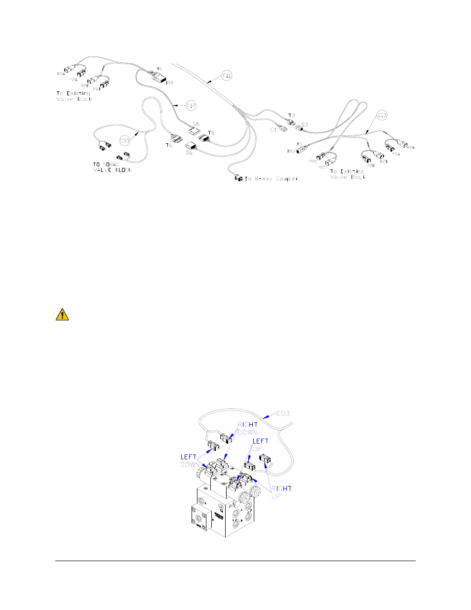
Figure 15: Cable Configurations: C03, C11, C12 and C13
6. Route C11 to the vicinity of the valve block at the rear of the sprayer. Note that the
R12/R6 connectors provide the hitch connection.
7. Connect the 6-pin shroud (S6) on C12 to the 6-pin tower (T6) on C11. Connect the 3-pin
shroud (S3) on C13 to the 3-pin tower (T3) on C11.
8. Route the free ends of C12 and C13 to the existing valve block. Insert all of the Deutsch
tees between the matching valve connections. The function is labeled on the branch wire
for each tee.
It is recommended to connect P2C and R2C (Bypass) on C13 to the existing
valve block even though it is not used.
9. Connect the 6-pin tower on C03 to the 6-pin shroud on C11. Connect the 2-pin
connectors on C03 to the NORAC valve block, as shown in Figure 16.
10. The connectors on the valve cable (C03) are marked RIGHT UP, LEFT UP, RIGHT
DOWN and LEFT DOWN. Cables labeled with UP go on the same side as the
hydraulic hoses.
Figure 16: Valve Cable Connections