NORAC UC4.5-BC-JD6 User Manual
Page 22
20
20
8. Connect the 6-pin shroud on C04 to 6-pin tower on C12.
9. Connect the 6-pin tower on the valve cable (C03) to 6-pin shroud on C12.
10. C12 has a screw terminal. It must be connected to the frame of the sprayer. Scrape any
paint off the frame where the terminal is mounted. A good location is the bolt holding the
JD wiring harness next to the large connector at the rear of the sprayer frame.
The terminal must be attached directly to the sprayer frame NOT the parallel
linkage. An improper ground can cause UC4.5 Spray Height Control system
malfunctions.
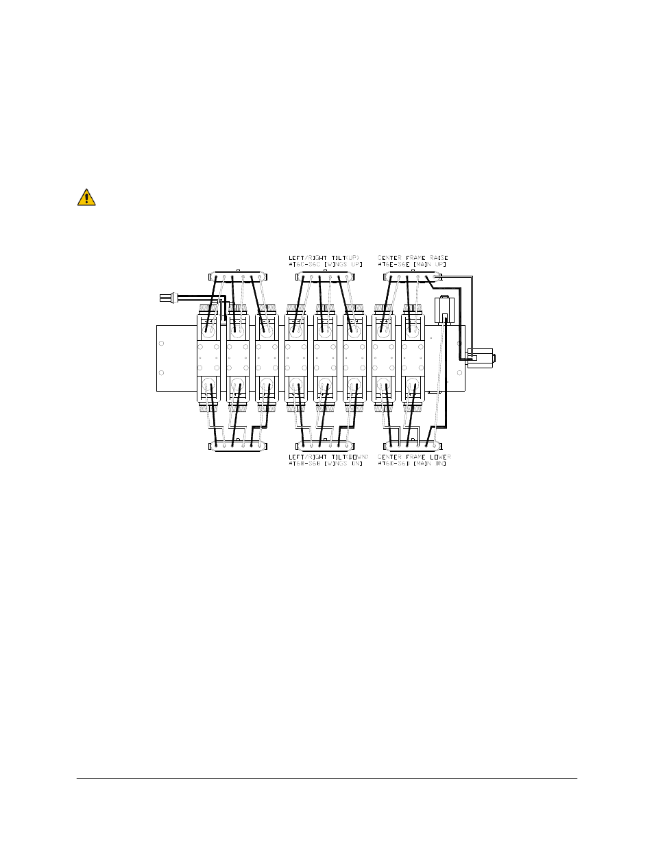
Figure 22: Sprayer Wiring Harness Identification
12. Locate the main John Deere wiring harness at the rear of the sprayer near the sprayer valve
block. The sprayer wiring harness identification is shown in Figure 22.
13. Disconnect the JD harness connections and connect in the junction cable (C12). (Refer to
Figure 22 and Figure 23)
Center Frame:
Disconnect the 2 right most 6-pin connectors of the JD harness.
Tee T6D-S6D of C12 into the rearward connection. S6D is labeled “Main Dn”.
Tee T6E-S6E of C12 into the forward connection. S6E is labeled “Main Up”.
Left and Right Booms:
Disconnect the 2 center 6-pin connectors of the JD harness.
Tee T6B-S6B of C12 into the rearward connection. S6B is labeled “Wings Dn”.
Tee T6C-S6C of C12 into the forward connection. S6C is labeled “Wings Up”.