Control elements – MUTEC MC-5 User Manual
Page 9
> > > > > > > > > > > > > > > > > > > > > > > > > > > > > > > > > > > > > > > > > > > > > > > > > > > > > > > > > > > > > > > > > > > >
88
\
B E D I E N E L E M E N T E
B E D I E N E L E M E N T E
B E D I E N E L E M E N T E
> > > > > > > > > > > > > > > > > > > > > > > > > > > > > > > > > > > > > > > > > > > > > > > > > > > > > > > > > > > > > > > > > > > >
CONTROL ELEMENTS
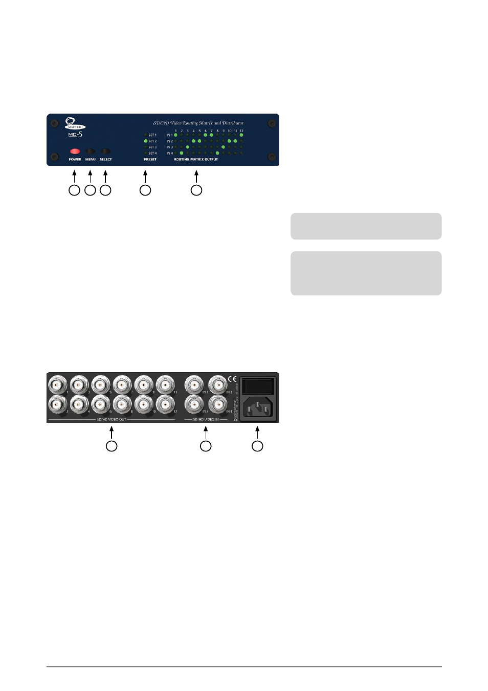
MC-5 Front Panel
1 POWER
This red LED lights up when the unit is switched on with the rear panel
POWER switch (on condition that the adjusted voltage matches your local
voltage).
2 MENU
Use this key to access the different function menus.
3 SELECT
Use this key to select a function from a specific function menu.
4 PRESET
This functional menu lets you choose one of the four available output
presets.
5 ROUTING MATRIX OUTPUT
Within this functional menu you can route the four inputs individually to
the 12 outputs.
For detailed specifications on all terminals,
refer to the »Pin Assignment of the
Connectors« and »Technical Data« in the
chapter APPENDIX.
Refer to the OPERATIONS chapter for more
information.
9
MC-5 Rear Panel
3
2
1
1 SD/HD VIDEO OUT
These outputs transfers SD bi-level or HD tri-level video signals. Every of the
four inputs can be individually assigned to one or more of these outputs.
For adjusting these outputs see chapter OPERATION.
2 SD/HD VIDEO IN
This inputs can receive SD bi-level or HD tri-level video signals. They can be
indivudually routed to one or more of the 12 outputs. For routing of these
inputs see chapter OPERATION.
3 MAINS IN, Power Switch + Mains connector (IEC)
This is the main switch for switching the device on and off. Connect the
supplied IEC power cable to the device‘s mains connector. Make sure that
the power switch is turned off before connecting the device to your power
source finally. Line voltages within the range of 90…260 V with a frequency
of 50 or 60 Hz can be applied. The internal power supply will automatically
make all necessary adjustments.
Heed the SAFETY INSTRUCTIONS at the beginning of this manual!
4
3
2
5
1