About tides, Installation, Online manual and help – Mutable Instruments Tides User Manual
Page 2: Front panel
About Tides
Tides is, depending on your point of view, a volt-
age-controlled (looping) AR/AD generator which
can reach audio frequencies; or a dynamically
waveshaped synth voice with the ability to go into
subsonic territories.
Installation
Tides requires a -12V / +12V power supply (2x5
pins connector). The red stripe of the ribbon cable
(-12V side) must be oriented on the same side as
the “Red stripe” marking on the board.
The power consumption is as follows:
-12V: 5mA ; +12V: 55mA.
Online manual and help
The manual can be found online at
mutable-instruments.net/modules/tides/manual
For help and discussions, head to
mutable-instruments.net/forum
A
B
C
D
E
F
G
1
2
3
4
5
8
9
10
11
7
6
12
13
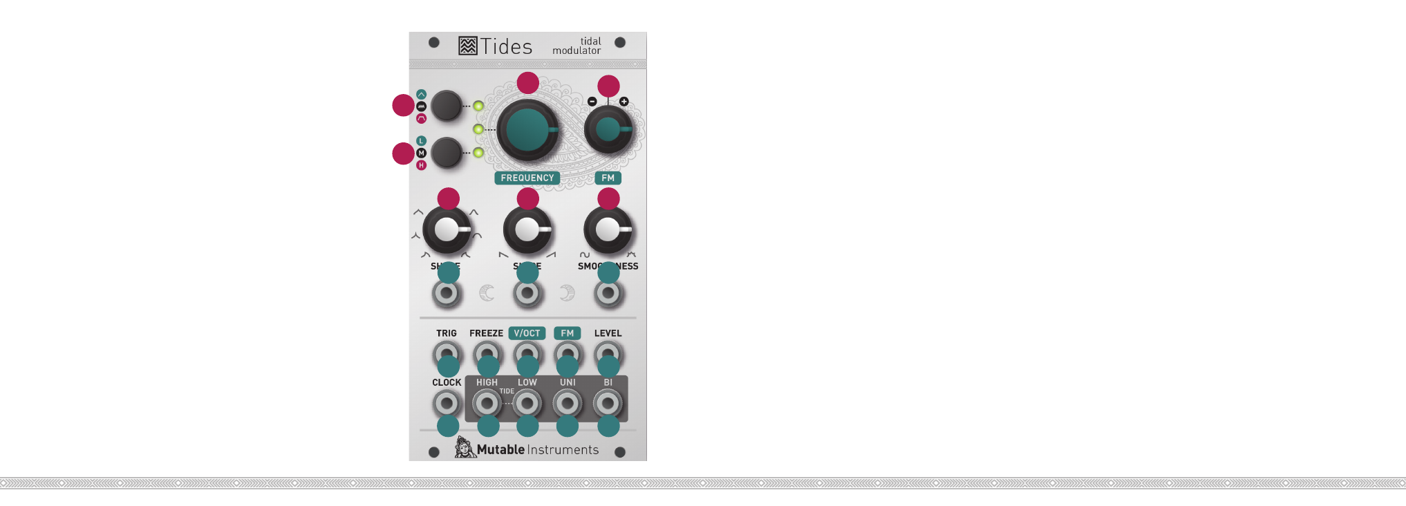
Front panel
Controls
A.
Mode selection. Goes back and forth between
one-shot AD (green LED), looping (LED off), and
one-shot AR (red LED) modes.
B.
Range selection. Goes back and forth between
very low (green LED), low (LED off), and audio (red
LED) range.
C.
Frequency/rate control.
D.
Attenuverter for the FM input. When no sig-
nal is patched into the FM input, serves as a fine
tuning control.
E.
Waveshape of the ascending and descending
segments.
F.
Ratio between the duration of the ascending and
descending segments.
G.
Curve transformation. From 12 o’clock to 7
o’clock (counter-clockwise), applies a 2-pole low-
pass filter. From 12 o’clock to 5 o’clock (clockwise),
applies a wavefolder.
Inputs and Outputs
1. 2. 3.
CV inputs for shape, slope, and smoothness
controls.
4.
Trigger/Gate input. On a rising edge, resets the
waveform and starts the ascent. On a falling edge,
and in AR mode, starts the descent.
5.
Freeze input. A gate signal applied on this input
can stop the envelope/oscillator and hold the
signal.
6.
V/Oct input. 1V/Oct frequency/rate control.
7.
FM input, attenuated and inverted by the attenu-
verter (D).
8.
Waveform amplitude CV - normalled to a con-
stant 8V source.
9.
Clock input for PLL or tap tempo operation.
10. 11.
End of attack (high tide) and end of decay/
release (low tide) logic outputs.
12. 13.
Unipolar (0 to 8V) and bipolar (-5V to 5V)
outputs.