Milwaukee Tool 5243 User Manual
Page 3
4
5
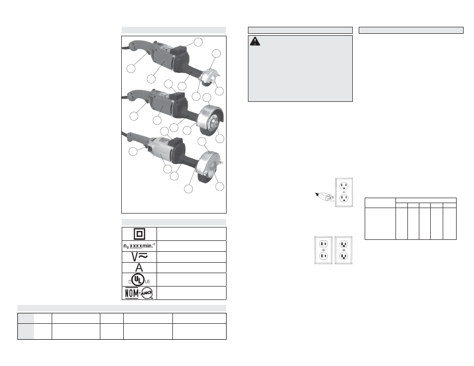
Functional Description
accessory. Corners, sharp edges or bouncing
have a tendency to snag the rotating accessory
and cause loss of control or kickback.
• Do not attach a saw chain woodcarving blade or
toothed saw blade. Such blades create frequent
kickback and loss of control.
Safety Warnings Specific for Grinding
Operations:
• Use only wheel types that are recommended for
your power tool and the specifi c guard designed
for the selected wheel. Wheels for which the
power tool was not designed can not be adequately
guarded and are unsafe.
• The guard must be securely attached to the
power tool and positioned for maximum safety,
so the least amount of wheel is exposed to-
wards the operator. The guard helps to protect
operator from broken wheel fragments and ac-
cidental contact with wheel.
• Wheels must be used only for recommended
applications. For example: do not grind with the
side of cut-off wheel. Abrasive cut-off wheels are
intended for peripheral grinding, side forces applied
to these wheels may cause them to shatter.
• Always use undamaged wheel fl anges that are
of correct size and shape for your selected
wheel. Proper wheel fl anges support the wheel
thus reducing the possibility of wheel breakage.
Flanges for cut-off wheels may be different from
grinding wheel fl anges.
• Do not use worn down wheels from larger power
tools. Wheel intended for larger power tool is not
suitable for the higher speed of a smaller tool and
may burst.
Additional Safety Warnings
• Maintain labels and nameplates. These carry
important information. If unreadable or missing,
contact a MILWAUKEE service facility for a free
replacement.
• WARNING: Some dust created by power sanding,
sawing, grinding, drilling, and other construction
activities contains chemicals known to cause can-
cer, birth defects or other reproductive harm. Some
examples of these chemicals are:
• lead from lead-based paint
• crystalline silica from bricks and cement and other
masonry products, and
• arsenic and chromium from chemically-treated
lumber.
Your risk from these exposures varies, depending
on how often you do this type of work. To reduce
your exposure to these chemicals: work in a well
ventilated area, and work with approved safety
equipment, such as those dust masks that are spe-
cially designed to fi lter out microscopic particles.
Cat. No. 5211 3"
Cat. No. 5223 5"
Cat. No. 5243 6"
1. Trigger
2. Motor housing
3. Spindle housing
(insulated handle)
4. Guard assembly clamp
5. Faceplate
6. Guard assembly
7. Tool rest
8. Spindle Nut
1
2
3
6
7
4
8
1
2
4
3
5
6
7
1
2
3
4
5
6
7
Double Insulated
No Load Revolutions per
Minute (RPM)
Volts Alternating Current/
Direct Current
Amps
Underwriters Laboratories, Inc.,
United States and Canada
Mexican Safety
Standards
Symbology
Specifi cations
No Load
RPM
14500
7000
5700
Volts
AC/DC
120
120
120
Cat.
No.
5211
5223
5243
Grounding Req. or
Double Insulated
Double Insulated
Double Insulated
Grounding Required
Arbor Size Diameter,
Threads
3/8" - 24
5/8" - 11
5/8" - 11
Wheel Size Thickness,
Diameter
1/2" x 3"
1" x 5"
1" x 6"
Grounded tools require a three wire extension
cord. Double insulated tools can use either a two
or three wire extension cord. As the distance from
the supply outlet increases, you must use a heavier
gauge extension cord. Using extension cords with
inadequately sized wire causes a serious drop in
voltage, resulting in loss of power and possible tool
damage. Refer to the table shown to determine the
required minimum wire size.
The smaller the gauge number of the wire, the
greater the capacity of the cord. For example, a 14
gauge cord can carry a higher current than a 16
gauge cord. When using more than one extension
cord to make up the total length, be sure each cord
contains at least the minimum wire size required. If
you are using one extension cord for more than one
tool, add the nameplate amperes and use the sum
to determine the required minimum wire size.
Guidelines for Using Extension Cords
• If you are using an extension cord outdoors,
be sure it is marked with the suffi x “W-A” (“W”
in Canada) to indicate that it is acceptable for
outdoor use.
• Be sure your extension cord is properly wired
and in good electrical condition. Always replace
a damaged extension cord or have it repaired by
a qualifi ed person before using it.
• Protect your extension cords from sharp objects,
excessive heat and damp or wet areas.
READ AND SAVE ALL
INSTRUCTIONS FOR FUTURE USE.
Recommended Minimum Wire Gauge
for Extension Cords*
Extension Cord Length
* Based on limiting the line voltage drop to fi ve volts
at 150% of the rated amperes.
Nameplate
Amperes
0 - 2.0
2.1 - 3.4
3.5 - 5.0
5.1 - 7.0
7.1 - 12.0
12.1 - 16.0
16.1 - 20.0
25'
18
18
18
18
16
14
12
75'
18
18
16
14
12
10
100'
18
16
14
12
10
150'
16
14
12
12
50'
18
18
18
16
14
12
10
EXTENSION CORDS
Grounded Tools: Tools with Three Prong Plugs
Tools marked “Grounding Required” have a three
wire cord and three prong grounding plug. The
plug must be connected to a properly grounded
outlet (See Figure A). If the tool should electrically
malfunction or break down, grounding provides a
low resistance path to carry electricity away from
the user, reducing the risk of electric shock.
The grounding prong in the plug is connected
through the green wire inside the cord to the
grounding system in the tool. The green wire in the
cord must be the only wire connected to the tool's
grounding system and must never be attached to
an electrically “live” terminal.
Your tool must be plugged into an appropri-
ate outlet, properly installed and grounded in
accordance with all codes and ordinances.
The plug and outlet should look
like those in Figure A.
Double Insulated Tools:
Tools with Two Prong Plugs
Tools marked “Double Insulated” do not require
grounding. They have a special double insula-
tion system which satisfi es OSHA requirements
and complies with the applicable standards of
Underwriters Laboratories, Inc.,
the Canadian Standard Asso-
ciation and the National Elec-
trical Code. Double Insulated
tools may be used in either of
the 120 volt outlets shown in
Figures B and C.
Fig. B Fig. C
Fig. A
GROUNDING
WARNING
Improperly connecting the
grounding wire can result in the risk of
electric shock. Check with a qualifi ed electri-
cian if you are in doubt as to whether the
outlet is properly grounded. Do not modify
the plug provided with the tool. Never remove
the grounding prong from the plug. Do not
use the tool if the cord or plug is damaged. If
damaged, have it repaired by a MILWAUKEE
service facility before use. If the plug will not
fi t the outlet, have a proper outlet installed by
a qualifi ed electrician.