Crestron tps-6x-ds docking station for the tps-6x – Crestron electronic TPS-6X-DS User Manual
Page 9
Crestron TPS-6X-DS
Docking Station for the TPS-6X
Connectors, Controls & Indicators
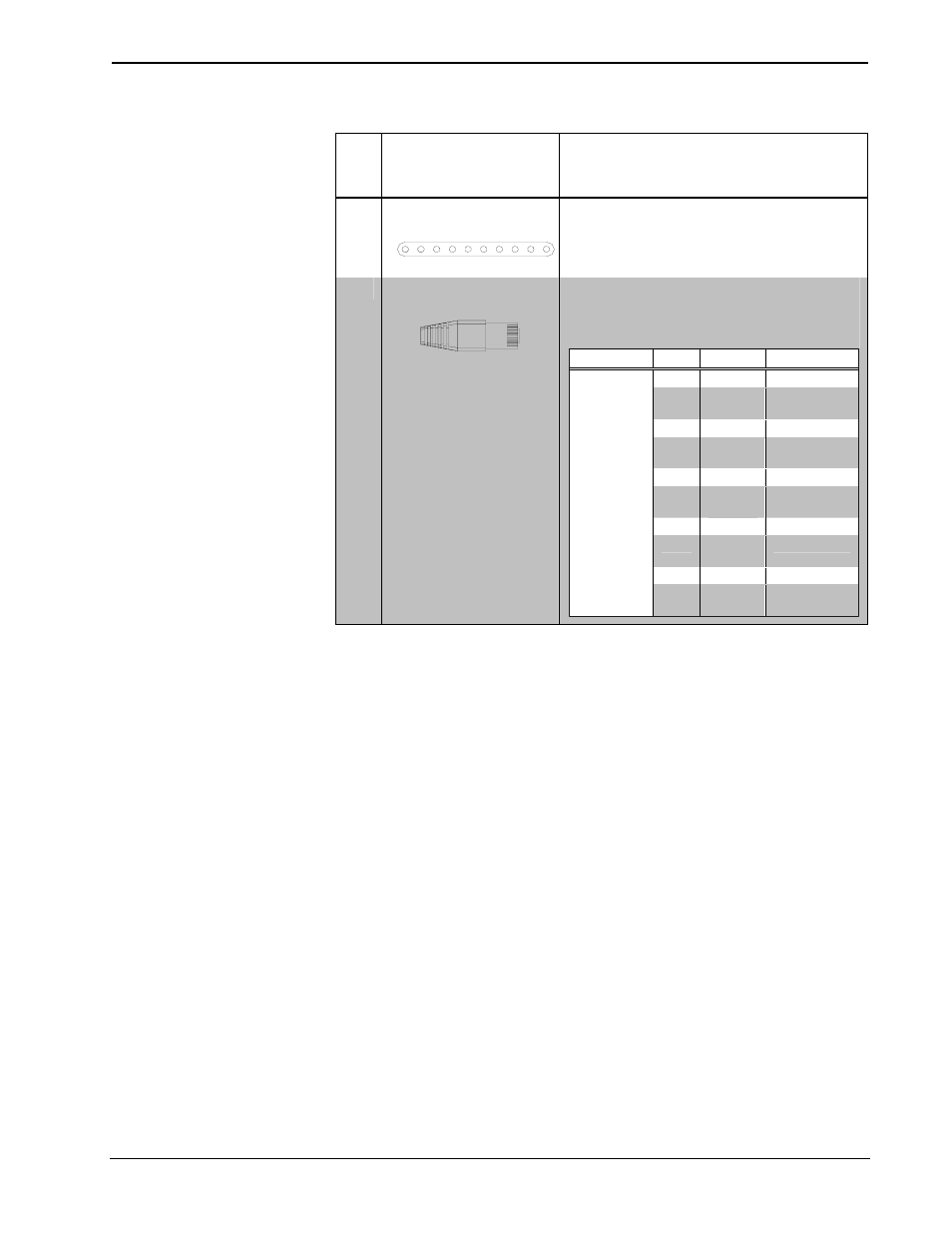
#
CONNECTORS
1
,
CONTROLS &
INDICATORS
DESCRIPTION
1
TOUCHPANEL
CONNECTOR
(1) 10-pin connector for connecting to
touchpanel.
2
INTERFACE MODULE
CONNECTOR
2
(1) Integral 9 foot (2.75 meter) cable with
10-pin RJ-50 male connector;
Connects to TPS-6X-IMCW Interface Module
(included).
TYPE
PIN
COLOR
SIGNALS
1
Gray
Ground
2
Orange/
White
Ethernet TX+
3
Orange
Ethernet TX-
4
Green/
White
Ethernet RX+
5
Blue
Cresnet Y
6
Blue/
White
Cresnet Z
7
Green
Ethernet RX-
8
Brown/
White
Diff Video +
9
Brown
Diff Video -
10-Position
RJ-50
10
Gray/
White
Power
12V/24V
1. The interface module connector fixed onto the TPS-6X-DS is to be connected to the TPS-6X-IMCW’s
TO PANEL port.
2. To determine which is pin 1 on the cable, hold the cable so that the end of the ten pin modular jack is
facing away from you, with the clip down and copper side up. Pin 1 is on the far left.
Operations Guide – DOC. 6576B
Docking Station for the TPS-6X: TPS-6X-DS
• 5