Make Noise Teleplexer User Manual
Page 5
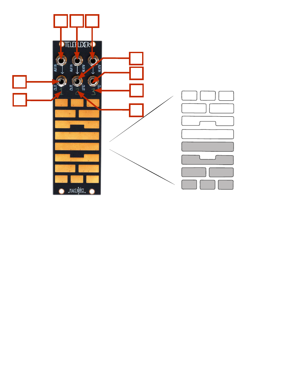
Teleplexer Interface
1.
Aux. IN CH. 1: direct coupled signal input, continuously added to CH. 1
2.
Aux. IN CH. 2: direct coupled signal input, continuously added to CH. 2
3.
Aux. IN CH. 3: direct coupled signal input, continuously added to CH. 3
4.
OUT CH. 1: direct coupled signal output for CH. 1
5.
OUT CH. 2: direct coupled signal output for CH. 2
6.
OUT CH. 3: direct coupled signal output for CH. 3
7.
CH. 1 Signal Indication: channel number lights to show level and polarity of signal.
Green is positive signal and red is negative signal.
8.
CH. 2 Signal Indication: channel number lights to show level and polarity of signal.
Green is positive signal and red is negative signal.
9.
CH. 3 Signal Indication: channel number lights to show level and polarity of signal.
Green is positive signal and red is negative signal.
1
3
4
6
2
8
5
9
7
1
2
3
1+2
1+3
20
2+3
1+3
1+2
2+3
1
3
1+2+3
1+2+3
2
10 11 12
13
14
15
16
10
17
18
19
20
21 22 23