Tapping uses chart for water boilers – Crown Boiler 32 User Manual
Page 41
41
39
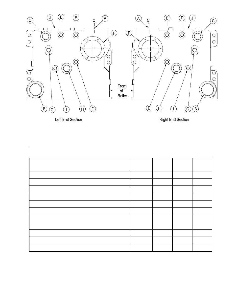
Tapping Uses Chart For Water Boilers
1
Component Description
Tapping
Tapping Standard
CSD-1
Location
Size (in) Equipment Package
Supply Piping
A
3
N
N
Return Piping
B
3
N
N
Pressure Relief Valves
C
2
1-1/2
Y
Y
Combination Pressure / Temperature / Altitude Gauge
E
1/2
Y
Y
Hydrolevel #750 Probe Low Water Cut-Off
Supply Riser
-
N
Y
Honeywell L4006A Pressure Limit Control
D
1/2
Y
Y
Honeywell L4006E Manual Reset Pressure Limit Control
(To Be Installed On The Same Side As L4006A)
Boiler Drain Valve
B
3
Y
Y
Cover Plate
F
-
Y
Y
Optional Tankless Heater
F
-
N
N
1. Trim May Be Installed On Either End Section.
2. Use The Tapping Located On The End Not Equipped With Trim For The Pressure Relief Valve.
Supply Riser
-
N
Y
Table 7
Figure 29: Water Boiler Tapping Locations