Out of production – LAARS LLS-1 - Instruction Manual User Manual
Page 6
Page 6
LAARS HEATING SYSTEMS
Water Level Sensor - J9
This connection is for a Laars Low Water
Cutoff only. (Other low water cutoff devices must be
connected to Aux SW - J32.) This connection is
made at the factory on units that are ordered with the
Low Water Cutoff option or other options that
include a Low Water Cutoff and is made in the field
when being added after the unit is on site.
Draft Pressure Switch - T4
When a draft fan is installed, a draft pressure
switch must be connected to ensure that the fan is
operating before the boiler is allowed to fire. Some
boilers and water heaters have built-in fans, and this
connection will be made to the units internal draft
switch. Remove factory-installed jumper when
connecting draft pressure switch.
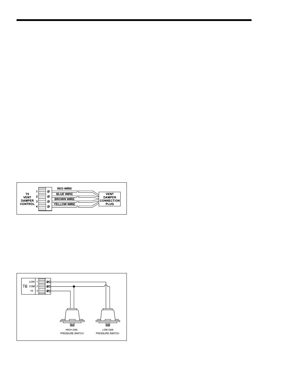
Vent Damper Control - T5
Vent dampers for units that require them
(Mighty Therm HH & PH, 175-250) are equipped
with a harness that requires wiring to the LLS
through the Vent Damper Control connection. See
Figure 2. Remove factory installed jumper when
connecting vent damper.
High & Low Gas Pressure Switches - T6
Figure 3. High and Low Gas Pressure Switch
Connection.
Figure 2. LLS Vent Damper Connection.
On pump-mounted units, this connection is
made at the factory. To interlock a pump to the LLS
for non-pump-mounted units, with the addition of
Laars high voltage (110V) relay & wire harness, use
this connection. One end of the wire harness connects
to J20 and the other end connects to the relay. A
separate 110V source is then connected through the
relay to the pump. This connection will handle
pumps as large as 1hP, 110V, single phase. The LLS
can be programmed to post-purge the pump and
monitor current draw through the relay.
DHW Pump Control - J19
This feature works with the Laars DHW
sensor only. To interlock a domestic water pump
(the pump between the heater and the storage tank) to
the LLS, with the addition of Laars high voltage
(110V) relay, wire harness, and DHW sensor, use
this connection. One end of the wire harness connects
to J19 and the other end connects to the relay. The
Laars DHW sensor must be connected to T3. A
separate 110V source is then connected through the
relay to the pump. This connection will handle
pumps as large as 1hP, 110V, single phase. The LLS
can be programmed to post-purge the pump and
monitor current draw through the relay.
Aux Sw - J32
This connection is made at the factory if
additional switches are ordered with the unit. If not,
field-supplied safety switches can be connected here.
Safety switches that must prevent the boiler from
firing must be connected here, or in series with the
boiler wiring, and NOT through the Field-Interlock
connection.
Alarm Relay - J29
This is a normally open 24VAC relay
connection, and is not a dry contact. With this alarm
relay, the user will have a 24VAC source for building
automation system alarms, bells, buzzers, or any
other alarm device, 8VA maximum.
Draft Inducer Relay - J28
When a boiler or water heater has a built-in
draft fan, this connection will be made at the factory.
For field-supplied draft fans or power venters with
the addition of Laars relay, the user can make a
connection here which, upon a call for heat, will call
the fan to operate. The LLS can be programmed to
pre-purge and/or post-purge the fan. Important note:
When this connection is used, a draft pressure switch
must be installed at connection T4 to prove the fan is
operating before the unit fires.
Vent Damper Relay - J27
When a heater is built with high and low gas
pressure switches, this connection is made at the
factory. When adding gas pressure switches in the
field, wire them per Figure 3. Remove factory-
installed jumper when connecting gas pressure
switches.
Main Pump Control - J20
OUT OF
PRODUCTION