2 initial start-up – LAARS Mighty Therm AP (Sizes 500-1825) - Installation, Operation and Maintenance Instructions User Manual
Page 11
Mighty Therm Commercial Pool Heating Boiler
Page 11
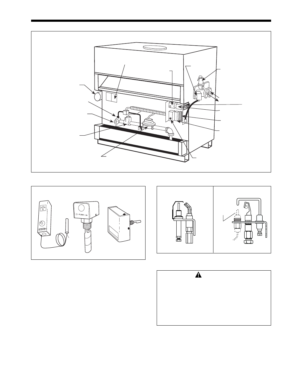
Figure 11 - Control Locations
Rating Plate
Manual
Pilot
Valve
Water
Circulating
Pump
Safety
Gas
Valve
Operating/Safety
Gas Valve
Ignition Control
Flow
Switch
Pressure
Relief
Valve
Power
(On/Off/Auto)
Switch
Pump Time
Delay Relay
Operating
Controls
Terminal Strip
In
Out
Hi-Limit
Manual
Main
Gas Valve
Figure 12 - Safety Components
Manual Reset
High Limit
Flow
Switch
Low Water
Cutoff
(Optional)
Figure 13 - Pilot Burners
Thermo-
couple
Spark Ignition
Standing Pilot
5. Flow
Switch:
Standard on all AP pool heating heaters. The switch
is mounted in a tee fi tting on the outlet header.
This is a paddle type switch which is defl ected
by the water fl ow in the fi tting. Any condition
which interrupts or decreases the fl ow through the
secondary loop will shut down the burners.
6.
Low Water Cut Off (optional):
The low water cut off automatically shuts off heater
whenever water level in the heat exchanger drops
below probe level. It is located in the inlet header,
and is a manually reset device.
3.2 Initial Start-Up
WARNING
Do not use this appliance if any part has
been under water. Immediately call a qualifi ed
service technician to inspect the heater. The
possible damage to a fl ooded appliance can
be extensive and present numerous safety
hazards. Any appliance that has been under
water must be replaced.
Newly constructed pools may have low pH, and higher
levels of calcium hardness or construction debris. Do
not allow pool water to circulate through the pool heater
until the water has been fi ltered to remove all debris,