LAARS Mighty Therm AP (Sizes 2000-5000) - Installation, Operation and Maintenance Instructions User Manual
Page 8
Page 8
LAARS Heating Systems
Therefore, the temperature difference between
the inlet and out pipes will be so small as to be
difficult to sense by touching the two pipes.
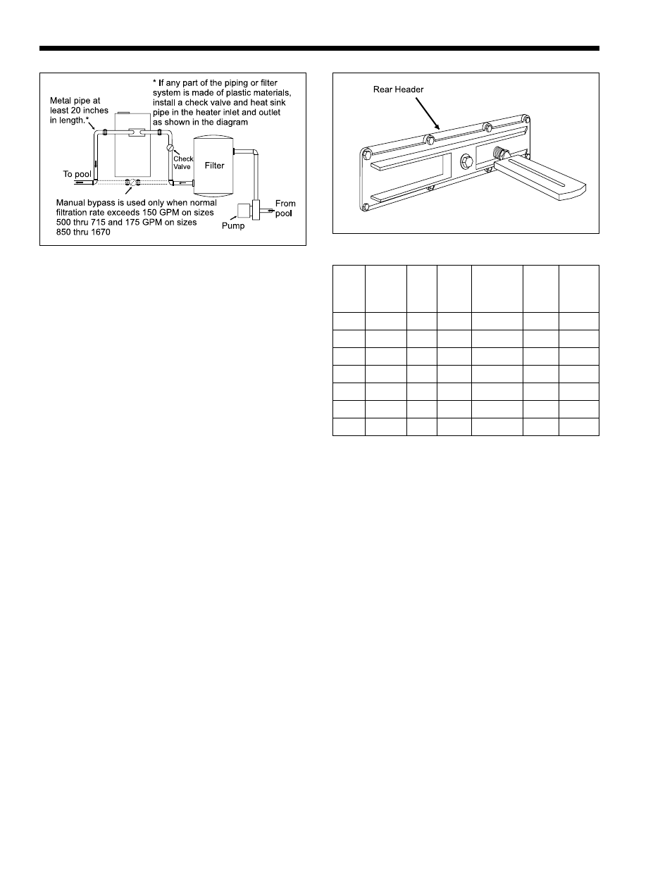
2I. Boiler By-Pass Piping
All Model AP pool boilers are equipped with an
automatic flow control valve. Do not install a manual
bypass valve unless the normal filtration rate exceeds
300 GPM. If the normal filtration rate exceeds that
figure:
1.
Install the manual bypass valve as illustrated in
Figure 7.
2.
Install a thermometer in the threaded opening in
the rear header as shown in Figure 8.
3.
Set the manual bypass valve as follows:
a.
Clean or backwash the filter completely.
b.
Close the manual bypass valve completely.
c.
Close the boiler’s main gas valve.
d.
Start the filtration system with all valves set
for normal filtration.
e.
After 3 minutes, record the thermometer
reading (this is the pool water temperature).
f.
Open main gas valve and turn the
thermostat to its highest setting to start the
boiler.
g.
Gradually open the bypass valve until the
temperature difference shown in column 6
of Table 4 is achieved. For example, if the
temperature reading in Step “e” was 60
degrees, and the boiler is a Model 3500, the
thermometer should read 75 degrees. Make
sure this temperature difference remains
constant for at least 5 minutes.
h.
Remove the handle from the bypass valve
to prevent anyone from changing the
setting. The automatic flow control valve
will maintain proper flow through the
boiler regardless of the reduced water flow
due to a dirty or clogged filter.
2J. Automatic Chlorinators
A concentration of chlorine in the boiler can be
very destructive. Therefore, the following rules
regarding the installation and operation of automatic
chlorinators must be followed.
1.
The chlorinator should be installed so that it
introduces the gas or solution downstream from
the boiler.
2.
The chlorinator should be wired so that it cannot
operate unless the filter pumps running.
3.
The chlorinator should be provided with an anti-
syphoning device so that when the pump shuts
off, chlorine will not syphon back into the boiler.
4.
When the chlorinator is installed in the system
where the chlorine flows through the boiler,
corrosion can occur. Excessive concentrations of
chlorine, caused by improper adjustment or
failure of the chlorination equipment, can cause
boiler damage which is not covered by the
warranty.
2K. Pressure Switch
The pressure switch on the boiler is factory set at
4 psi. Do not tamper with the switch unless the boiler
is installed more than 3 feet below the surface of the
Figure 7. Manual By-Pass Installation.
Figure 8. Thermometer Location.
Bypass
Min.
Max. Temp.
Spring
Flow
Bypass
Rise
Indoor Outdoor Part
Color
Req'd
Valve
at Rear
Size
Size
No.
Code (GPM)Cap. (GPM) Header
2000
------
S220
Black
110
300
15
2450
2200
S221
White
134
300
15
3050
2800
S221
White
167
300
15
3500
3200
S222 Brown
191
300
15
4050
3600
S222 Brown
221
300
15
4500
4000
S222 Brown
246
300
15
5000
4500
S222 Brown
273
300
15
Table 4. By-Pass Valve Adjustments.