9 wiring to current controlled modulating motors, 10wiring to voltage controlled modulating motors, 11wiring the lockout inputs – LAARS MC4EXT - Install and Operating Manual User Manual
Page 3: Limit circuit typical for each stage
MC Extension Box
Page 3
Class 1 voltages must enter the enclosure
through a different opening from any Class 2 voltage
wiring.
1.8 Wiring to 135
Ω
Ω
Ω
Ω
Ω Modulating Motors
The MCX can be equipped to operate up to eight
135
Ω modulating motors.
Each pair of stages, E&F, G&H, I&J, and K&L,
are controlled by one output board.
Wire as shown in Figure 7 and Table 1.
1.9 Wiring to Current Controlled
Modulating Motors
The MCX can be equipped to operate up to eight
4-20 mA modulating motors.
To program the control for 4-20 mA output, see
the MC I/O manual (MC I/O Manual, System Startup
settings).
Apply the supplied label marked 4-20 mA below
the output terminals.
Each pair of stages, E&F, G&H, I&J, and K&L,
are controlled by one output board.
The MCX sources 24VDC excitation voltage for
the 4-20mA signal.
Wire as shown in Figure 7 and Table 1.
1.10Wiring to Voltage Controlled
Modulating Motors
The EXM can be equipped to operate up to eight
0-5 V, 0-10V, 1-5V, or 2-10V modulating motors.
To select the range, 0-5V, 0-10V, 1-5V or 2-
10V, see the MC I/O manual (MC I/O Manual,
System Startup settings).
Apply the supplied label marked Voltage below
the output terminals.
Each pair of stages, E&F, G&H, I&J, and K&L,
are controlled by one output board.
Wire as shown in Figure 7 and Table 1.
1.11Wiring the Lockout Inputs
A closure across the pair of MCX LOCKOUT
INPUT terminals informs the MC that the particular
stages's boiler, chiller, etc. has encountered a safety
limit and can not be restarted without a manual reset.
The MC will not activate or modulate a Stage in
Lockout.
A pair of LOCKOUT INPUT terminals is
provided for each stage.
The Lockout signal must be a dry contact closure
from the boiler, chiller, etc. controlled by that stage's
output.
The LOCKOUT INPUTS are dry contacts only.
No voltage can be placed across the terminals.
Wire the Lockout signals to their respective
STAGE terminals (see Figure 8):
- STAGE E to Lockout Input terminals B1&B2
- STAGE F to Lockout Input terminals B3&B4
- STAGE G to Lockout Input terminals B5&B6
- STAGE H to Lockout Input terminals B7&B8
- STAGE I to Lockout Input terminals B9&B10
- STAGE J to Lockout Input terminals B11&B12
- STAGE K to Lockout Input terminals B13&B14
- STAGE L to Lockout Input terminals B15&B16
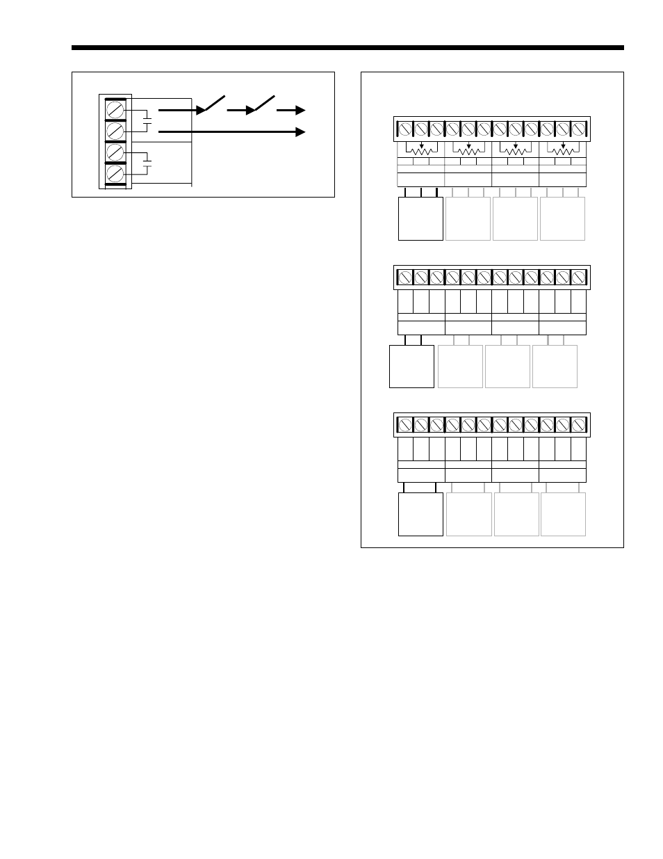
Figure 6. Stage Wiring.
3
4
F
2
E
1
Limit Circuit
Typical for
each stage
Figure 7. Control Voltage Wiring.
B
C2
C3
C4
C5
C6
C7
C8
C9 C10 C11 C12
R
W
B
135
W
Motor
B
R
W
135
W
Motor
B
R
W
135
W
Motor
B
R
W
135
W
Motor
R
W
135
W
E
B
R
W
135
W
F
B
R
W
135
W
G
B
R
W
135
W
H
4 - 20mA
Motor
Current
E
Current
F
Current
G
-
GND
+
24
NC
Current
H
C1
C2
C3
C4
C5
C6
C7
C8
C9 C10 C11 C12
C1
-
GND
+
24
NC
-
GND
+
24
NC
-
GND
+
24
NC
-
+
4 - 20mA
Motor
-
+
4 - 20mA
Motor
-
+
4 - 20mA
Motor
-
+
Voltage
Motor
Voltage
E
Voltage
F
Voltage
G
V+
NC
GND
Voltage
H
C2
C3
C4
C5
C6
C7
C8
C9 C10 C11 C12
C1
V+
NC
GND
V+
NC
GND
V+
NC
GND
GND
Voltage
Motor
Voltage
Motor
Voltage
Motor
V+
GND
V+
GND
V+
GND
V+