0 duct design and burner mounting, 0 start-up and adjustment, Figure 7–pressure measurement figure 6–pilot cock – Eclipse Combustion AH User Manual
Page 6
6
Eclipse AirHeat v1.0 - Installation Guide No. 140, 11/4/03
3.0
Duct Design and Burner Mounting
Duct Design
See Figure 5 for typical mounting arrangements and duct designs.
Support
The mounting flange or brackets supplied with an AH burner are capable of sup-
porting the weight of the burner and blower. The AH burner case itself is de-
signed to support the weight of the blower, so the blower does not require inde-
pendent support.
Valve Train Support
Support valve trains independently of the burner.
Gas Piping
Use flexible nipples to allow for thermal expansion of the burner.
Check Valve Piping
Gas flow through the check valve must be horizontal. See Figure 3.
Gas Piping Standards
Gas piping must comply with American National Standard entitled “National Fuel
Gas Code”* (NFPA No. 54 or ANSI Z223.1), or must be acceptable to the author-
ity having jurisdiction.
Wiring Standards
Electrical wiring must comply with the National Electric Code*, (NFPA Std. 70 or
ANSI-CI 1981), or must be acceptable to the authority having jurisdiction.
*Available from:
National Fire Protection Association
American National Standard Inst.
Batterymarch Park
1430 Broadway
Quincy, MA 02269
New York, New York 10018
4.0
Start-Up And Adjustment
Initial Settings
Adjust the linkage of the gas control valve so that when heat is called for, the
valve is 10° from fully open, and when cooling is required, the valve is approxi-
mately 5° from fully closed.
Close all manual gas cocks.
With the pilot cock handle in the closed position, remove the top screw and turn
the adjusting screw five turns out from fully closed. See Figure 6.
Start Blower
Start the combustion air blower on the burner. Check the rotation to make sure it
is correct. If not, have a qualified electrician rewire the blower for proper rotation.
Start Circulating Fan
Start the duct circulating fan.
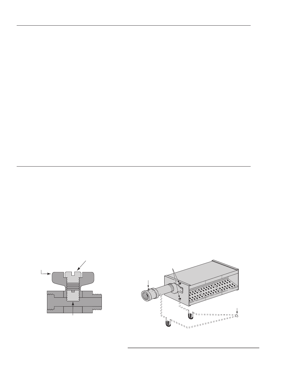
Figure 7–Pressure Measurement
Figure 6–Pilot Cock
Top Screw
Handle
(Shown in
Open Position)
Adjusting Screw
(Clockwise for less pilot gas,
Counterclockwise for more pilot gas)
Gas
Pressure
Tap
Duct Tap
10" to 20"
Downstream of Burner
Air Pressure
Taps (2)