Carrier 50TCA04-A07 User Manual
Page 28
28
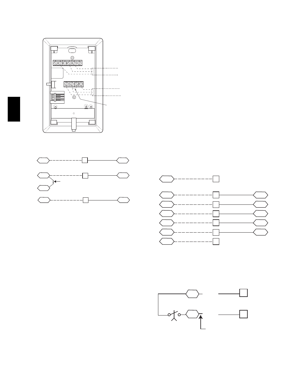
Connect T--56 -- See Fig. 38 for T--56 internal
connections. Install a jumper between SEN and SET
terminals as illustrated. Connect T--56 terminals to TB1
terminals 1, 3 and 5 (see Fig. 39).
2
3
4
5
6
1
SW1
SEN
SET
Cool
Warm
BRN (GND)
BLU (SPT)
RED(+)
WHT(GND)
BLK(-)
CCN COM
SENSOR WIRING
JUMPER
TERMINALS
AS SHOWN
BLK
(T56)
C08202
Fig. 38 -- T--56 Internal Connections
SEN
J6-7
J6-6
1
3
TB1
PL
SEN
SET
Jumper
TB1
PL
J6-5
5
SET
C08213
Fig. 39 -- PremierLink T56 Sensor
Connect Thermostat — A 7--wire thermostat connection
requires a 24--v power source and a common connection.
Use the R and C terminals on the LCTB’s THERMOSTAT
connection strip for these. Connect the thermostat’s Y1,
Y2, W1, W2 and G terminals to PremierLink TB1 as
shown in Fig. 40.
If the 50TC unit is equipped with factory--installed smoke
detector(s), disconnect the factory BLU lead at TB1--6
(Y2) before connecting the thermostat. Identify the BLU
lead originating at LCTB DDC--1; disconnect at TB1--6
and tape off. Confirm that the second BLU lead at TB1--6
remains connected to PremierLink J4--8.
If the 50TC unit has an economizer system and
free--cooling operation is required, a sensor representing
Return Air Temperature must also be connected
(field--supplied and installed). This sensor may be a T--55
Space Sensor (see Fig. 36) installed in the space or in the
return duct, or it may be sensor PNO 33ZCSENSAT,
installed in the return duct. Connect this sensor to TB1--1
and TB1--3 per Fig.
37. Temperature--resistance
characteristic is found in Table 5.
Configure the unit for Thermostat Mode — Connect to the
CCN bus using a CCN service tool and navigate to
PremierLink Configuration screen for Operating Mode.
Default setting is Sensor Mode (value 1). Change the
value to 0 to reconfigure the controller for Thermostat
Mode.
When the PremierLink is configured for Thermostat
Mode, these functions are not available: Fire Shutdown
(FSD), Remote Occupied (RMTOCC), Compressor Safety
(CMPSAFE), Supply Fan Status (SFS), and Filter Pressure
Switch (FILTER).
Economizer controls —
Outdoor Air Enthalpy Control (PNO HH57AC077) --
The enthalpy control (HH57AC077) is available as a
field--installed accessory to be used with the EconoMi$er2
damper system. The outdoor air enthalpy sensor is part of
the enthalpy control. (The separate field--installed
accessory return air enthalpy sensor (HH57AC078) is
required for differential enthalpy control. See below.)
Locate the enthalpy control in the economizer hood.
Locate two GRA leads in the factory harness and connect
these leads to enthalpy control sensors 2 and 3. See Fig.
41. Connect the enthalpy control power input terminals to
economizer actuator power leads RED (connect to TR)
and BLK (connect to TR).
G
J4-12
J4-10
J4-8
Y1
Y2
2
R
R
4
6
J4-6
J4-4
W2
C
8
10
C
SPACE
THERMOSTAT
PL
LCTB
THERMOSTAT
W1
TB1
LCTB
THERMOSTAT
C08119
Fig. 40 -- Space Thermostat Connections
6
7
LCTB
ECON
3
2
Enthalpy
Switch
GRA
GRA
Factory Wiring Harness
C08218
Fig. 41 -- Enthalpy Switch (HH57AC077) Connections
The outdoor enthalpy changeover setpoint is set at the
enthalpy controller.
50TC