Carrier 50TCA04-A07 User Manual
Page 16
16
6. For units with an economizer, the sampling tube is in-
tegrated into the economizer housing but the connec-
tion of the flexible tubing to the sampling tube is the
same.
C08127
Fig. 22 -- Return Air Sensor Operating Position
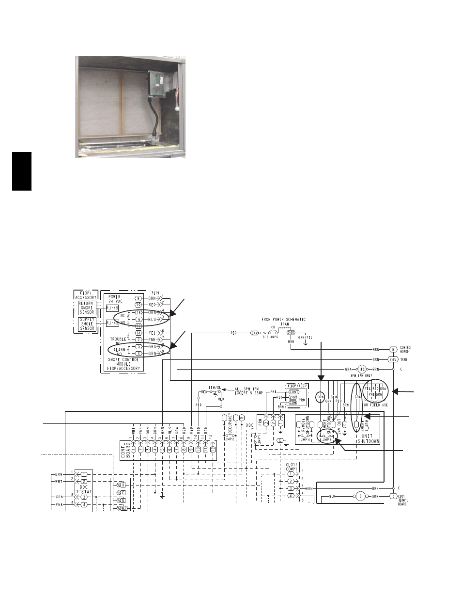
FIOP Smoke Detector Wiring and Response
All units: FIOP smoke detector is configured to
automatically shut down all unit operations when smoke
condition is detected. See Fig. 23, Smoke Detector
Wiring.
Highlight A: JMP 3 is factory--cut, transferring unit
control to smoke detector.
Highlight B: Smoke detector NC contact set will open on
smoke alarm condition, de--energizing the ORN
conductor.
Highlight C: 24--v power signal via ORN lead is removed
at Smoke Detector input on LCTB; all unit operations
cease immediately.
PremierLink Control: Unit operating functions (fan,
cooling and heating) are terminated as described above. In
addition:
Highlight D: On smoke alarm condition, the smoke
detector NO Alarm contact will close, supplying 24--v
power to GRA conductor.
Highlight E: GRA lead at Smoke Alarm input on LCTB
provides 24--v signal. This signal is conveyed to
PremierLink FIOP’s TB1 at terminal TB1--6 (BLU lead).
This signal initiates the FSD sequence by the PremierLink
control.
Using Remote Logic: Five conductors are provided for
field use (see Highlight F) for additional annunciation
functions.
Additional Application Data — Refer to Catalog No.
HKRNKA--1XA for discussions on additional control
features of these smoke detectors including multiple unit
coordination. See Fig. 23.
A
E
F
C
D
B
C08246
Fig. 23 -- Typical Smoke Detector System Wiring
50TC