Using atx power switch – CyberResearch CPEN GX-333-X User Manual
Page 78
CPEx GX-333-X
CyberResearch
®
CPU Cards
76
©Copyright 2007 CyberResearch, Inc.
The following notes show how to connect ATX Power Supply to the embedded
board.
1.
Using ATX Power Switch
NOTE:
The following diagram describes an ATX power connection for the 1.10
version of the CPEx GX-333-X. To connect the 1.11 version of the CPEx
GX-333-X to an ATX power supply, use the CN6 connector instead of
the CN4 connector shown below. Refer to the CN6 connector pinouts in
Chapter 2 for appropriate power button pin locations.
Step 1.
Disconnect the AC cord of the Power Supply from the AC source to prevent
sudden electric surge to the board.
Step 2.
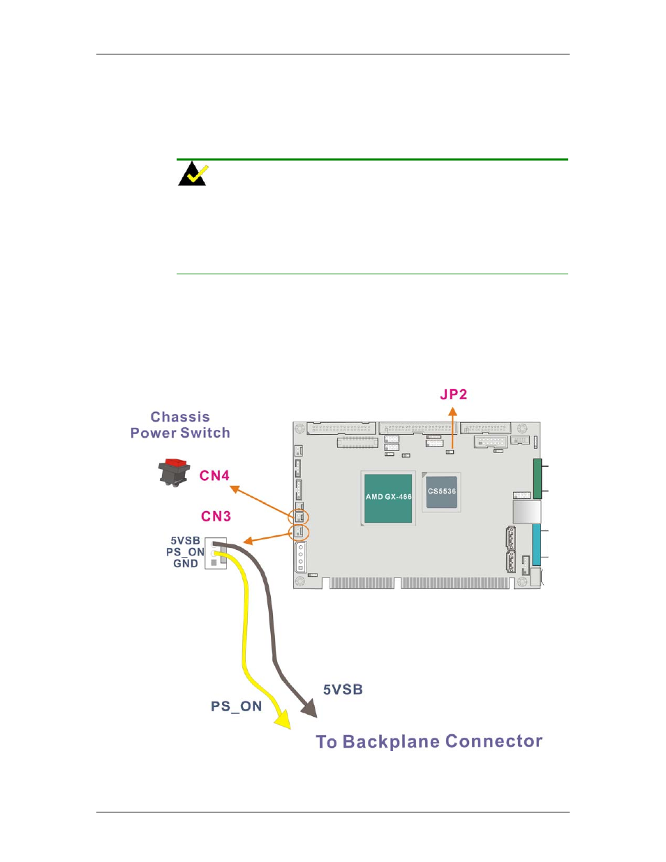
Remove the jumper cap on JP2.
Step 3.
Your ISA interface backplane should come with the associated 5VSB and
PS_ON pin connector. Usually connecting these two pins is sufficient. Also,
an ATX power feature cable should come ready with your backplane. Connect
CN3 to the associated connector on your backplane.
Figure B-34 ATX
Power
Connection
Step 4.
Connect CN4 to the chassis power switch.