Power, Description, Connectors & jumpers – Connect Tech PCIE/104 User Manual
Page 20
Connect Tech Xtreme/SBC PCIe/104 Single Board Computer and PCIe/104 Qseven Carrier Board - User Manual
Revision 0.02
20
Power
Description
The Xtreme/SBC is designed to be powered from an ATX type power supply, and support many of the
ACPI features like suspend to RAM. A CR1225 battery holder (P16) provides the VBAT for the Qseven
module.
The Xtreme/SBC generates 3.3V on board, to facilitate alternate powering options.
WARNING:
Do not attach a PCIe-104 power supply to P2 (the PCIe104 connector). These power
supplies typically generate 3.3V, which would conflict with the onboard 3.3V.
Other powering options include
A) +5V & +12V only: The ATX features can be bypassed by powering +5V_SB with same 5 volt supply
as the +5V input pins.
B) +5V only: similar to the above cause, but excluding the +12V which is used only by the backlight and
PCIe-104 connector. Before attempting this, verify that this configuration is appropriate for the target
installation.
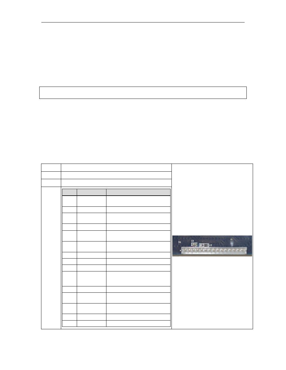
Connectors & Jumpers
Function ATX input power
Location P6
Type
JST B15B-EH-A
Pinout
Pin
Signal
Description
1
+5V
+5V input, powers onboard power
regulators & Qseven module
2
GND
Digital Ground
3
+5V
+5V input, powers onboard power
regulators & Qseven module
4
GND
Digital Ground
5
+5V
+5V input, powers onboard power
regulators & Qseven module
6
+5V_SB
+5V standby input, powers +3.3V
auxiliary power
7
GND
Digital Ground
8
PSON#
Power Supply On
9
PWROK
Power OK
10
+3.3V
+3.3V input, not used by
Xtreme/SBC. +3.3V is derived on
internally
11
GND
Digital Ground
12
+12V
+12V input, used by PCIe104 and
backlight
13
+12V
+12V input, used by PCIe104 and
backlight
14
GND
Digital Ground
15
-12V
-12V input, not used