Replacing the motherboard, Replacing the motherboard -15, Eplacing the – Conair MPA User Manual
Page 71: Otherboard, Important, Remove the mother- board from the shield, Reattach the shield and new motherboard, Set dip switches 7 and 8 to the correct unit type, Program output monitors on the new board, And replace with the new motherboard
UGH004/0999
microKool Portable Chillers
T
ROUBLESHOOTING
6-15
R
EPLACING THE
M
OTHERBOARD
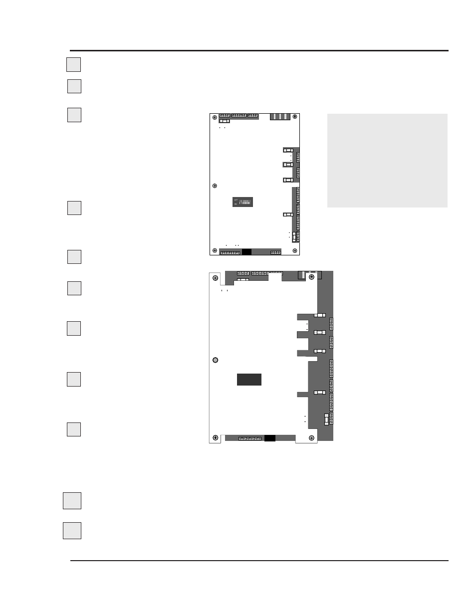
IMPORTANT:
Always
refer to the wiring dia-
grams that came with
your chiller to locate spe-
cific electrical compo-
nents. Illustrations in the
User Guide are intended
to be representative only.
Disconnect and lockout the main power supply.
Open the electrical enclosure door.
Turn the screw
on the front panel counterclockwise to open.
Mark or label each wire
connected to the mother-
board.
The orange shield is
labeled with the connection
information. You must label the
wires to ensure they are con-
nected to the correct terminals
on the new motherboard.
Disconnect the wires
from the motherboard by
pulling the terminal
blocks up.
Loosen the screws hold-
ing the orange shield.
Remove the mother-
board and shield
from the
electrical enclosure as a unit.
Remove the mother-
board from the shield
and replace with the new
motherboard.
Reattach the shield and
new motherboard
in the
electrical enclosure. Tighten
the screws.
Reconnect the terminal
blocks and wires to the
new board.
Make sure you align the terminal blocks with the correct
pins on the board. Push the terminal blocks onto the pins,
taking care not to bend any pins.
Set dip switches 7 and 8 to the correct unit type.
Set switch 7 to ON and switch 8 to OFF for chillers.
Program output monitors on the new board.
1
2
3
4
5
6
CONFIGURATION
DIP SWITCH
OFF
ON
4
3
2
1
4
3
2
1
UNLDR 1/ VENT 2 SOL +
UNLDR 1/ VENT 2 SOL
UNLDR 2/ COOL 1 SOL +
UNLDR 2/ COOL 1 SOL
F5
F4
F2
PUMP
PUMP
PUMP OL
PUMP OL
6
5
4
3
2
1
4
3
2
1
6
5
4
3
2
1
F3
4
3
2
1
F6
PMP AUX
PMP AUX
1FS/ PURGE/ COMP AUX
1FS/ COMP AUX
PUMPDOWN
PUMPDOWN
HEAT/COMP
HEAT/COMP
HTS/COMP OL
HTS/COMP OL
N
C
NC
NO
C
110V
ALARM
LLS/PURGE 3SOL
LLS/PURGE 3SOL +
PURGE 4SOL
PURGE 4 SOL +
3 PHASE INPUT
TCPL'S
SUP RET
A
C
IN 4
A
C
IN + 3
A
C
OUT 2
A
C
OUT + 1
F1
LLS/WPS
LLS/WPS
A
U
T
OST
AR
T
A
U
T
OST
AR
T
HPS/LPS
HPS/LPS
OPS
OPS
FST
A
T
FST
A
T
L1
L2
L3
6
5
4
3
2
1
4
3
2
1
Y
R
R
Y
1 2 3 4 5 6 7 8
1 2 3 4
(-2) CONTR
O
L
OPER PNL CABLE
+ 120 Ohm
+
TR
TR
GND
GND
+
TR
TR
120 Ohm
1
2
3
4
5
6
7
8
CONFIGURATION
DIP SWITCH
OFF
ON
4
3
2
1
4
3
2
1
F5
F4
F2
6
5
4
3
2
1
4
3
2
1
6
5
4
3
2
1
F3
4
3
2
1
3 PHASE INPUT
TCPL'S
SUP RET
A
C
IN 4
A
C
IN + 3
A
C
OUT 2
A
C
OUT + 1
F1
LLS/WPS
LLS/WPS
A
U
T
OST
AR
T
A
U
T
OST
AR
T
HPS/LPS
HPS/LPS
OPS
OPS
FST
A
T
FST
A
T
L1
L2
L3
6
5
4
3
2
1
4
3
2
1
Y
R
R
Y
1 2 3 4 5 6 7 8
1 2 3 4
(-2) CONTR
O
L
OPER PNL CABLE
+ 120 Ohm
+
TR
TR
GND
GND
+
TR
TR
120 Ohm
1
2
3
4
5
6
7
8
CONFIGURATION
DIP SWITCH
OFF
ON
UNLDR 2/ VENT 2 SOL +
UNLDR 2/ VENT 2 SOL
UNLDR 1/ COOL 1 SOL +
UNLDR 1/ COOL 1 SOL
F5
F4
F2
PUMP
PUMP
PUMP OL
PUMP OL
F3
F6
PMP AUX
PMP AUX
1FS/ COMP AUX
1FS/ COMP AUX
PUMPDOWN
PUMPDOWN
HEAT/COMP
HEAT/COMP
HTS/COMP OL
HTS/COMP OL
N
C
NC
NO
C
110V
ALARM
LLS/PURGE 3SOL
LLS/PURGE 3SOL +
PURGE 4SOL
PURGE 4SOL +
3 PHASE INPUT
TCPL'S
SUP RET
A
C
IN 4
A
C
IN + 3
A
C
OUT 2
A
C
OUT + 1
F1
LLS/WPS
LLS/WPS
A
U
T
OST
AR
T
A
U
T
OST
AR
T
HPS/LPS
HPS/LPS
OPS
OPS
FST
A
T
FST
A
T
L1
L2
L3
Y
R
R
Y
(-2) CONTR
OL
OPER PNL CABLE
+ 120 Ohm
+
TR
TR
GND
GND
+
TR
TR
120 Ohm
1
2
3
4
5
6
7
8
7
8
9
10
11