Power door lock wiring, 3 pin door lock plug, Pin 1: green – Crimestopper Security Products RS701 III User Manual
Page 9: Pin 2: red, Pin 3: blue, For additional diagrams - see page 11, Door lock diagrams with factory relays
POWER DOOR LOCK WIRING
3 PIN DOOR LOCK PLUG:
PIN 1: GREEN:
Sends a (-) Negative pulse for LOCK; Sends a positive pulse for UNLOCK
PIN 2: RED:
+12V Coil Power for external relays TERM 86. (If needed.)
PIN 3: BLUE:
Sends a (-) Negative pulse for UNLOCK; Sends a positive pulse for LOCK
DETERMINING DOOR LOCK TYPE:
There are several types of door lock systems in vehicles today. Below is listed the many types of common
locking systems:
Negative trigger: Most Japanese; Ford, New GM
Positive trigger: Many GM; Some Dodge/Chrysler/Plymouth
One wire dual voltage: Newer Dodge/Chrysler/Plymouth; Ford Probe
Reverse Polarity: Dodge/Chrysler/Plymouth; GM; Ford
Ground/open: Some Nissan; Subaru
Semi-automatic: Older Saab and Volvo
Electric vacuum pump: Pre 1995 Mercedes-Benz
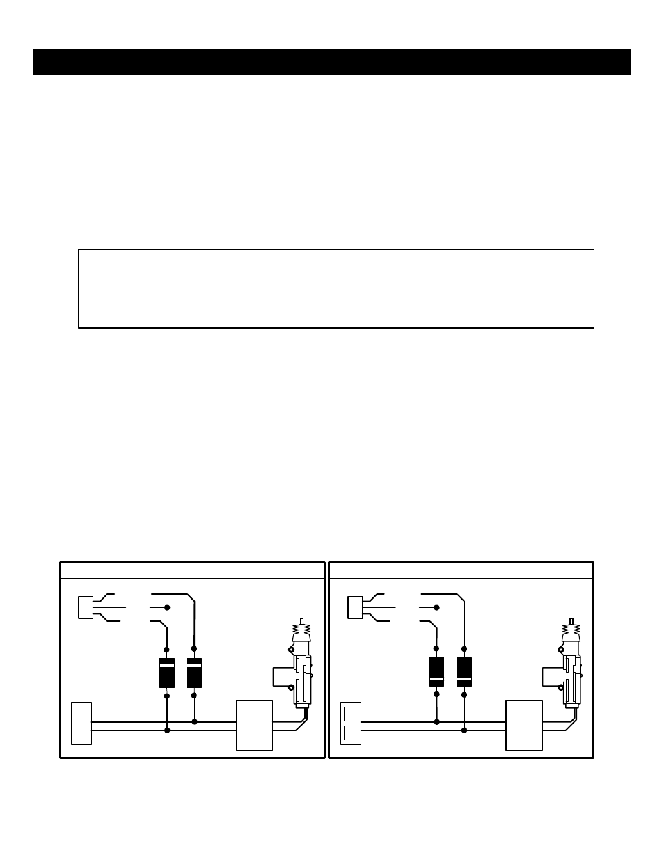
NEGATIVE TRIGGER DOORLOCK WIRING
POSITIVE TRIGGER DOORLOCK WIRING
GREEN
GREEN
RED
RED
BLUE
BLUE
DIODES
FACTORY
FACTORY
L
L
LOCK
LOCK
POWER
POWER
LOCKING
LOCKING
UL
UL
RELAYS
RELAYS
UNLOCK
UNLOCK
FOR ADDITIONAL DIAGRAMS - SEE PAGE 11
IN4001
DIODES
IN4001
DOOR LOCK DIAGRAMS WITH FACTORY RELAYS
WARNING: You must determine the type of locking system the vehicle has before connecting
any wires. Incorrect connection will result in damage to the remote start and/or vehicle locking
system. Use 1-amp diodes as shown in the diagram below when tapping into a Factory
Positive or Negative door lock system to protect the output transistors against a dead short
from some types of Factory locking systems.