Electric diagram, Maintenance of motors, Cleaning brass trim – Vermont Casting DEF33CE User Manual
Page 8: Wh = white bl = black re = red
- 8 -
MAINTENANCE OF MOTORS
The motors used on the fan and the drum assembly are
prelubricated for extended bearing life and require no
further lubrication. However, periodic cleaning/vacuuming
of the fan/heater is recommended.
Make sure that the power is turned off
before proceeding.
CLEANING BRASS TRIM
Clean the brass trim using a soft cloth, slightly dampened
with lemon oil and buff with a clean soft cloth. Do NOT use
brass polish or household cleaners as these products will
damage the brass trim. Lemon oil can be obtained at
supermarkets or hardware stores.
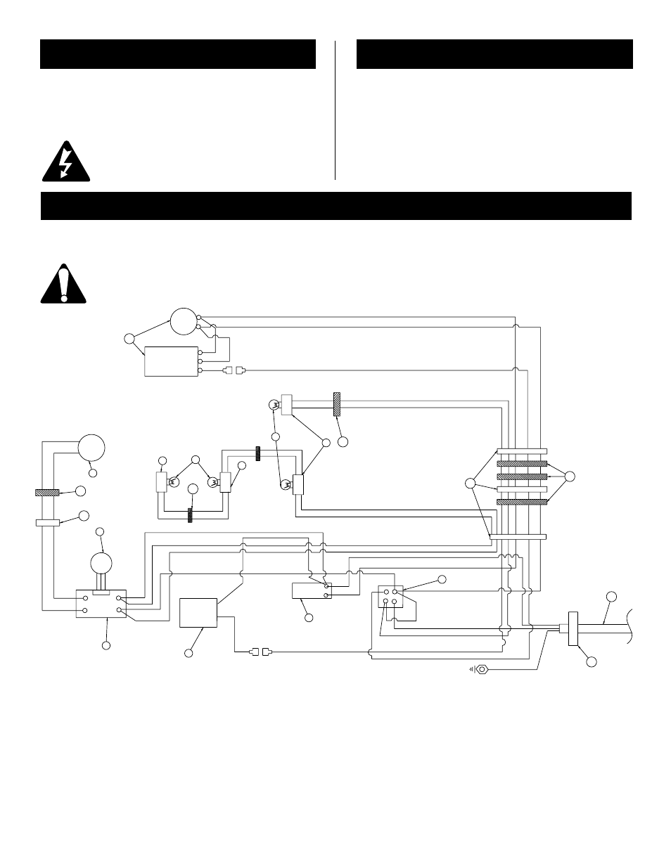
ELECTRIC DIAGRAM
Any electrical repairs or rewiring of this unit should be carried out by a licensed electrician in accordance with national and
local codes
If repairing or replacing any electrical component or wiring the original wire routing, colour coding and
securing locations must be followed.
Wiring Colour Code:
WH =
White
BL =
Black
RE =
Red
CFM Majectic Factory Wire Req'd
2.
Motor Variable Speed (12V/DC)
3.
potentiometer
4.
Speed Control
5.
Dimmer Switch Rotary
6.
Thermostat
7.
On / Off Switch
8.
Light Socket
9.
Light Bulb
10. Fan/Heater
11. Nylon Cable Tie
12. Grommet 7/8
2 WHITE
1 BLACK
4 WHITE
3 BLACK
6 WHITE
5 BLACK
11 YELLOW
8 RED
5 BLACK
6 WHITE
13 BLACK
8
10
11
11
9
9
8
8
2
12
11
3
4
5
6
7
12
11
13
14
MOTOR
DRUM
11 YELLOW
9 RED
8 WHITE
SPEED CONTROL
THERMO STAT
MOTOR
FAN
HEATER ELEMENT
DIMMER
POTENIOMETER
RED
10 BLACK
BLACK
7 BLACK
14 WHITE
8 WHITE
10003167