The rear panel, All tube guitar amplifiers – Crate Amplifiers ALL TUBE BV-129H User Manual
Page 5
5
125VAC, 50/60Hz T5A SLO-BLO
250VAC, 50/60Hz T2.5A SLO-BLO
AC LINE IN
AVIS:
RISQUE DE CHOC ELECTRIQUE.
NE PAS OUVRIR
CAUTION
RISK OF ELECTRIC SHOCK
DO NOT OPEN
WARNING:
TO REDUCE THE RISK OF FIRE OR
ELECTRICAL SHOCK, SO NOT EXPOSE THIS EQUIP-
MENT TO RAIN OR MOISTURE.
M a d e i n t h e U . S . A . b y • S L M E L E C T R O N I C S
1 4 0 0 F e r g u s o n A v e . • S t . L o u i s , M O . 6 3 1 3 3
MAIN
(USE FIRST)
EXT.
SPEAKERS
100 WATTS RMS
LINE OUT
IMPEDANCE
SELECTOR
8
16
SEND
TIP = CHANNEL SELECT
RING = EFFECTS LOOP
SLEEVE = GROUND
RETURN
EFFECTS
LOOP
FOOTSWITCH
R
T
S
T
S
R
27
26
25
24
23
21
22
19
20
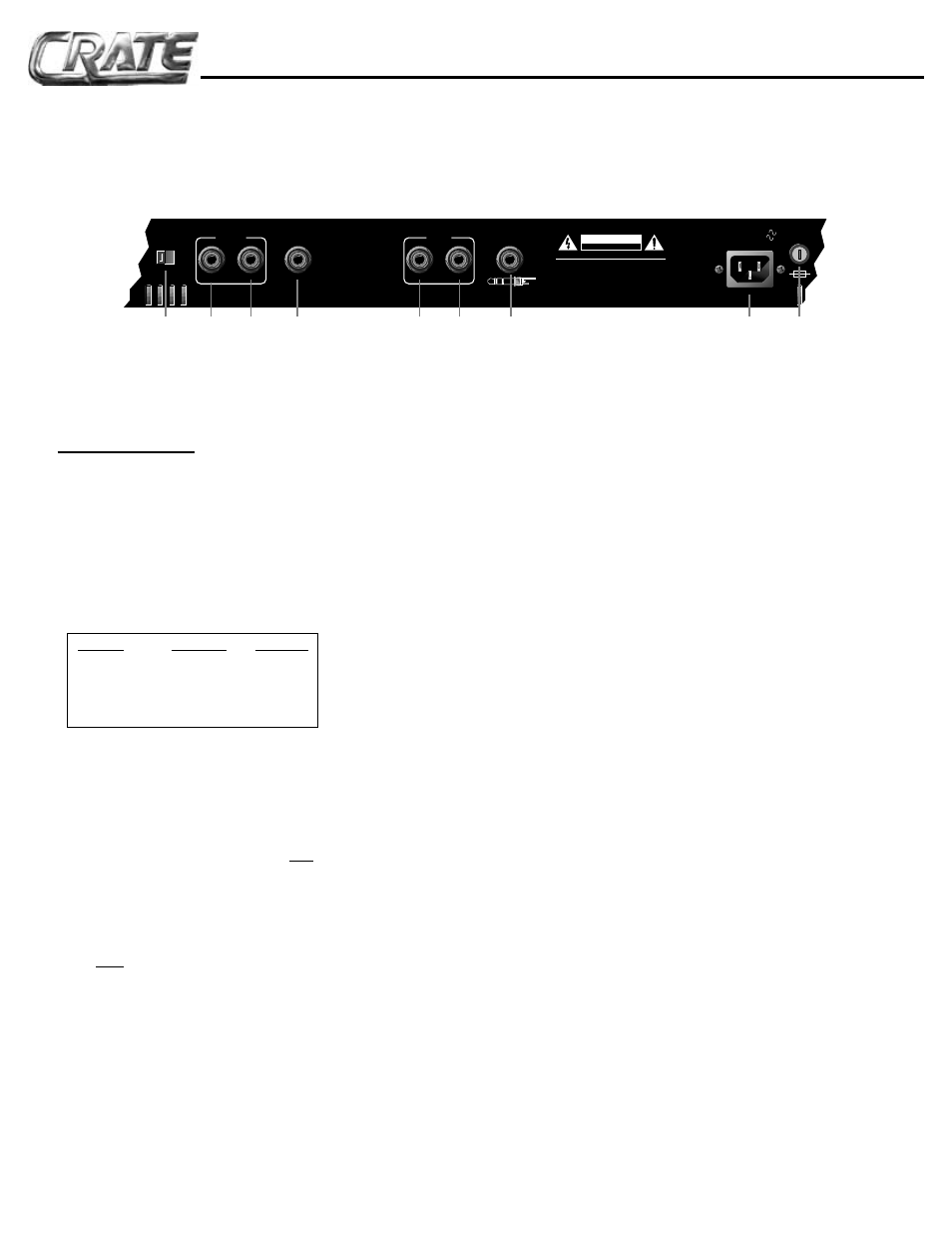
The Rear Panel:
19. IMPEDANCE SELECTOR: For the best
performance and least strain on your amplifier,
you MUST properly match the impedance of
your amplifier to that of your speaker cabinet(s).
Set the selector switch to the 8 or 16 ohm posi-
tion, depending on the total impedance of your
speaker cabinet(s). The chart below can help
you determine that impedance based on the fol-
lowing combinations of speakers connected in
parallel.
CAB. IMP.
# OF CABS.
TOTAL IMP.
8 OHMS
1
8 OHMS
16 OHMS
1
16 OHMS
16 OHMS
2
8 OHMS
32 OHMS
2
16 OHMS
32 OHMS
4
8 OHMS
20. MAIN SPEAKER JACK: Use this jack to
connect the amplifier to your primary speaker
cabinet by means of a heavy gauge speaker
cable. Always keep the impedance at 8 or 16
ohms, with the impedance selector switch (#19)
at the proper setting.
NOTE: Use the MAIN SPEAKER jack first.
Then, if an extension speaker is desired,
connect it to the EXT. SPEAKER jack.
21. EXT. SPEAKER JACK: Use this jack to
connect the amplifier to a secondary speaker
cabinetby means of a heavy gauge speaker
cable, after a speaker has been connected to
the main speaker jack (#20).
22. LINE OUT JACK: This 1/4” jack supplies a
line-level output signal from the power amp for
patching into a mixing board, recording console
or external amplifier. The signal is tapped direct-
ly from the speaker outputs, then attenuated
and electronically compensated to simulate the
sound of a “miked” cabinet.
23. EFFECTS LOOP RETURN: Connection
from an external effects device is made via this
jack. Connect a shielded instrument patch cord
from the output jack of the effect to the return
jack. This jack is active only when the effects
loop is switched in. The return jack also doubles
as a "power amp in" jack, to feed a line-level
signal directly into the BV-60H/120H's internal
power amp. This is useful when "slaving" two
amplifiers together.
24. EFFECTS LOOP SEND: Connection to an
external effects device is made via this jack.
Connect a shielded instrument patch cord from
the send jack to the input jack of the effect. This
jack is always active. The send jack also dou-
bles as a "preamp out" jack, to feed a post-eq,
pre-amplified signal to a mixing board, record-
ing console or external amplifier.
25. FOOTSWITCH JACK: Connect a stereo
1/4” (tip/ring/sleeve) here from a two-button
footswitch (such as the Crate CFP-2) for remote
control of channel switching and the effects
loop. The tip of the jack is for the channel
switching; the ring is for the effects loop. When
a footswitch is connected here, the front panel
channel select and effects loop switches are
disabled.
26. AC LINE IN: This grounded power cord is to
be plugged into a grounded power outlet, wired
to current electric codes and compatible with
voltage, power, and frequency requirements
stated on the rear panel. Do not attempt to
defeat the safety ground connection.
27. FUSE: This fuse protects the amplifier
against damages caused by overload condi-
tions in the unit. If the fuse fails, replace it only
with the same size and type as indicated on the
rear panel. If the fuse fails continually, the line
voltage may be incorrect, or the amp may need
servicing.
BV-60H / BV-120H
All Tube Guitar Amplifiers