ISP Technologies HDL 3112 User Manual
Page 6
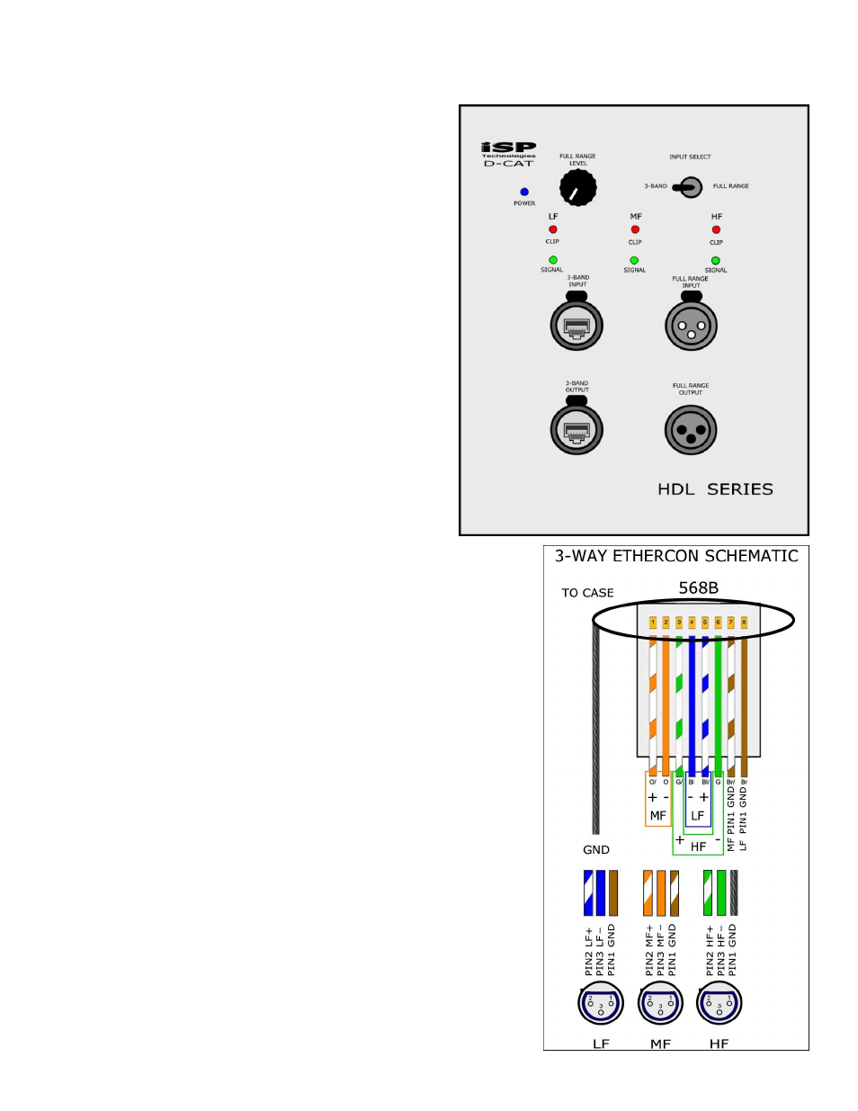
REAR PANEL CONNECTION DIAGRAM
The HDL 3112™ rear connection panel
provides both a single ETHERCON input
connector, which includes all 3 input signals
via a shielded CAT-5 connector and a single
XLR Full Range input. The XLR Full Range
input is processed internally to provide the
correct crossover points for the HDL3112. A
Full Range Level adjustment is provided to
adjust the level of each individual HDL3112,
note: this level control only works for the Full
Range input. For even more accurate time
alignment of the system, an external
processer can be used to provide both the
crossover points of the system and additional
system equalization. Outputs signals are
available for both ETHERCON 3-band signals if
using the ETHERCON input or XLR Full Range
output if the XLR input connector is used.
Both the ETHERCON 3-Band input and the
XLR Full Range input connectors include a
ground float circuit to help avoid ground loops
as a result of multiple cabinets connected in a
system. A 3-Band meter is provided to indicate when a
signal is present in each of the 3-Bands and when the
input signal is at the point of clipping in each band. The
input signal LED will light 21dB below the clip point and
will indicate a remaining headroom of 21dB in that
specific band. An external DSP Processor is required to
provide the correct crossover and system equalization
for the HDL 3112 system.
The diagram to the right shows the 3-WAY ETHERCON
Schematic for the input of the HDL 3112 Line Array
cabinet. The HDL 3112 requires the use of shielded
CAT-5 cable in order to provide a ground connection for
the input circuit. An ETHERCON input breakout cable is
available from ISP Technologies allowing for separate
XLR input connections for each of the 3-Band input
signals Low, Mid and High. If you make a custom input
cable you must follow the connection diagram shown to
ensure that the proper input signal is applied to the
correct band of the HDL 3112.