Theta footcontroller – ISP Technologies THETA 212 Combo User Manual
Page 11
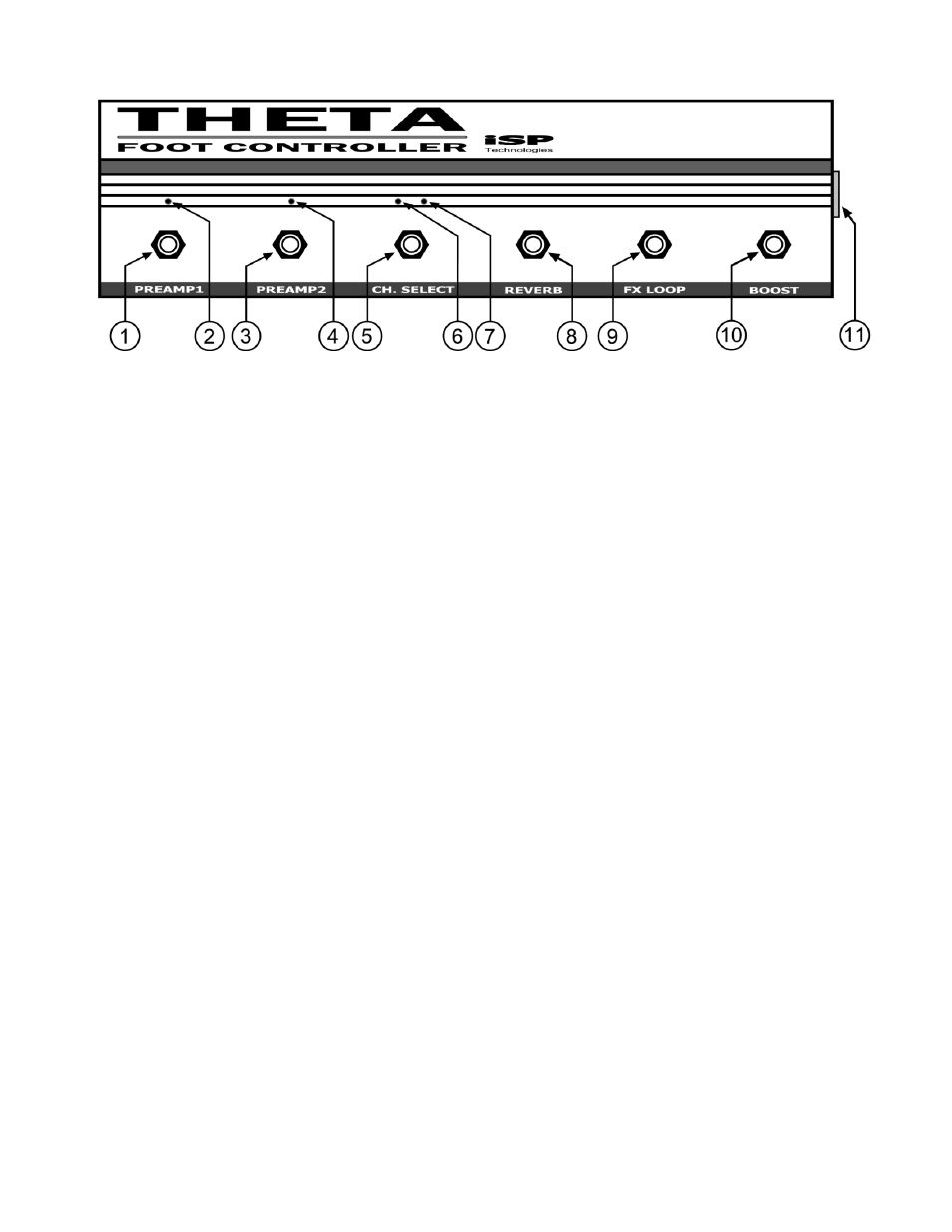
THETA FOOTCONTROLLER
1. PREAMP1 SWITCH
This switch turns on and off PREAMP1 the CLEAN channel preamp on the THETA.
2. PREAMP1 LED
When this LED in on PREAMP1 is active, switched on.
3. PREAMP2 SWITCH
This switch turns on and off PREAMP2 the DISTORTION channel preamp.
4. PREAMP2 LED
When this LED in on PREAMP2 is active, switched on.
5. CHANNEL SELECT SWITCH
This switch changes the channel selected between CLEAN and DISTORT.
6. CLEAN CHANNEL LED (RED)
This red LED indicates when the CLEAN CHANNEL is on and active.
7. DISTORT CHANNEL LED (BLUE)
This Blue LED indicates when the DISTORTION CHANNEL is on and active.
8. REVERB SWITCH
This switch turns on and off the THETA‘s internal digital reverb. NOTE: The digital reverb
will only function when the THETA FOOTCONTROLLER is connected and the reverb circuit
is switched on.
9. FX LOOP
This switch turns on and off the external effects loop allowing use of an external effects
processor. NOTE: The FX LOOP will only function when the THETA FOOTCONTROLLER is
connected and the FX LOOP is switched on.
10. BOOST
This switch turns on and off the THETA BOOST function allowing up to 6db of boost of
the output level of the amplifier.
11. D-SUB CONNECTOR
Connect the 15-pin D-SUB connector between this connector and the D-SUB connector
on the back of the THETA amplifier.