Application drawing, Camera end installation, Video – Interlogix VTP-H Series User Manual
Page 5: Control room installation
P/N 1069682 • REV 1.0 • ISS 14APR10
5 of 9
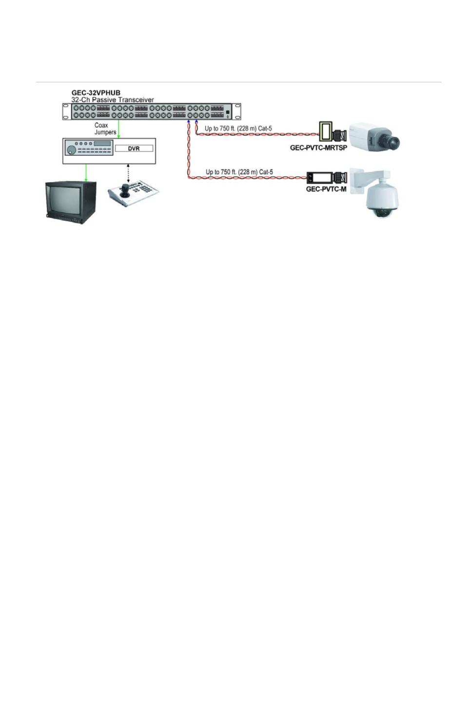
Application Drawing
Figure 1: Multi-channel short-range, passive-to-passive, UTP application
Camera End Installation
UTP:
• Connect the UTP wires carrying video signals to the terminal block input of
the receiver hub. If the UTP is terminated with a RJ-45 connector, then use
either the RJ-45 connector or the provided RJ-45 adapter to connect to the
transceiver hub.
• Make sure that the same UTP pair and polarity are used on both the transmit
and receive sides.
Video:
• Connect the baseband Video signal output of the camera to the BNC of the
Transceiver.
Control Room Installation
UTP:
• Connect the UTP wires carrying video signals to the terminal block input of
the receiver hub. If the UTP is terminated with a RJ-45 connector, then use
either the RJ-45 connector or provided RJ-45 adapter to connect to the
transceiver hub.
• Make sure that the same UTP pair and polarity are used on both transmit
and receive sides.