Intek RheoVac 950 User Manual
Page 13
- 11 -
TABLE II - Optiona l 4-20m A C onfig ura tion
Channel
Output Parameter
1
Actual volume flow
2
Total mass flow
3
W ater vapor flow
4
Pressure
5
W ater va por/A ir mass ratio
6
Relative saturation
7
Air in-leak
8
Tem perature
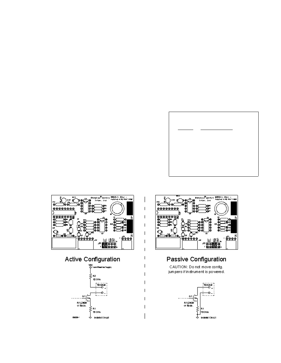
Figure 7 4-20 mA
Output Circuit
C.
Probe -
. .
CAUTION - Do not cross thread connection. The probe is supplied with a
convenient plug-in connector. The male side of the connector comes installed in the probe
junction box. The female side is usually shipped loose and must be installed onto the RS-
485 cable once it is run from the Distribution Box to the probe. A separate instruction sheet
comes with the connector, showing the wiring connections.
D.
Transmitter Box (optional) - For driving eight (8) remote 4-20 mA analog signals from one
RS-485 input port. (See Figure 8)
1. Connect the RS-485 communications/power cable from the distribution box (RS-485: white
and blue wires; 24Vdc power: red and black wires).
2. Connect up to eight (8) signal wire pairs to the indicated terminals for isolated 4-20mA
outputs.
3. Figure 8 provides the RheoVac wiring detail for
the 8 channel 4-20 mA outputs. Table II
provides the appropriate connection
identification. Model 950 transmitters are
configured as active (transmitter sources the
current) when shipped. To change to the passive
mode (receiver to source the current), extract
each small 4-20 board, find the JP1 pins, and
move the two jumpers from the "Act" pins to the
"Pass" pins (two positions to the right of factory
settings). Figure 7 shows the current output
circuit. The figure also illustrates the active
mode and the passive mode configurations.