El-600_vc34매뉴얼130423_2.pdf – IC Realtime 600TVL Mini Box Camera with D-WDR & DNR (EL600) User Manual
Page 2
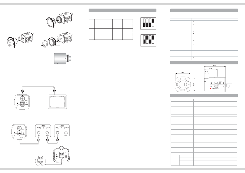
7. Function selection and Configuration of Switches
8. Troubleshooting
Before sending the camera out for repair, check the items below.
If the problem persists after checking these items, contact your service center.
Problems
Troubleshooting
Nothing appears on the screen.
· Please check the power connection.
· Please check the video signal line connection.
The video image is not clear.
· Please check if the lens or the outer glass is clean.
- Dirt or fingerprints on the lens can affect the image blooming or
reflection. Gently wipe any dirt fing erprints off the lens or the glass
with a soft cloth.
· Please check and adjust contrast feature of the monitor.
· Please check if the camera is exposed directly toward a bright light,
sunlight, or sun light reflecting area.
Please move the camera ’ s position in this case.
The screen is dark.
· Please check and adjust contrast feature of the monitor .
· If there is any interim equipment, set the Hi-z position properly and
check the terminals.
· Please check if the power supply is within the specification.
- When the cable connection requires a long distance, there may
need a higher power supply or an additional power/video
amplification.
The camera’s surface is too
hot and black stripes appear
on the screen.
· Please check if the power supply is regul a ted and is within the
standard requirement of the product.
The screen is flickering.
· Please check if the camera is facing directly toward sunlight or
fluorescent light.
10. Specification
9. Dimension (mm)
6-4. When using a CS-Mount lens
· Take off the protection cover.
· Take off the C-Mount Adaptor if any.
· Fix the lens by turning it clockwise.
6-3. When using a C-Mount lens
· Take off the protection cover.
· Assemble C-Mount adaptor.
· C-Mount Adaptor is included
in the package.
· Fix the lens by turning it clockwise.
C-Mount Adaptor
Cover
6-5. Video Monitor
Connect the Video out jack to the Video in jack on the monitor.
- Use good quality shielded coaxial video cable to avoid noise interference.
- Connect the cable with the power turned off.
6-6. Power
The power option of the camera is 12VDC only.
Use regulated DC 12V power supply and make
sure the power input is non polarized.
When the camera is used with multi-channel equipment or with more than 2
monitors, set impedance level switch on the interim equipment/monitors to Hi-Z
SRVLWLRQDQGPDNHVXUHWKHODVWPRQLWRUWRSRVLWLRQ
ͨͦש
ͨͦש
CCD CAMERA
CCD CAMERA
MONITOR
Use the lens connector shown in the following figure.
If the dimensions of the connector are
not correct, it may damage the camera, or the
lens may not be installed firmly.
If the lens is too heavy, the camera becomes
unbalance and there may be problems.
Use a lens to meet the camera.
When adjusting the Automatic Level Control(ALC)
of an auto iris lens, use Av mode if available.
If you use the Pk mode, the picture brightness may
change continuously.
ත Caution
INTERIM EQUIPMENT
OR MONITOR
LAST MONITOR
7-1. 4 way Dip Switch
7-2. Switch functions and adjustment
ྙ ESC(Electronics Shutter Control)
In this mode, Shutter Speed is controlled 1/60 ~ 1/100,000 sec.(NTSC) and
1/50 ~ 1/100,000 sec.(PAL)
ྚ BLC(Back Light Compensation)
Under bright lighting conditions from behind the subject, the camera will close the
iris automatically and the subject gets darker. Select BLC to ON to counteract this.
In normal lighting conditions, select BLC to OFF. It is set to OFF as a factory
standard.
ྛ AGC(Automatic Gain Contol)
Use this mode for dark illumination or at night. If the AGC Max. is selected the
camera increases the video signals to maximum so that the picture looks brighter.
At Max. mode, unnecessary noise is aloso increased and the picture many display
noise on the screen. This is normal.
It is set to ACG Nor. as a factory standard.
ྜ Flickerless
This is used only when there is a difference in frequency between the power
system(50Hz) and TV system(60Hz). In this case, flicker is occurred on the
monitor and set the mode to FL ON.
In most countries other than Japan do not need this set up.
It is set to FL Off as a factory standard.
ྜྷ White Balance
Use the White Balance to adjust the screen color.
ATW(Auto Tracking White Balance) mode is generally used and is suitable for
viewing a screen with one or various colors mixed on the background.
Push Lock mode is suitable when the object’s background is in high color
temperature(Ex. Clear sky, Sunset and so on)
When the S/W is positioned at the VI or DC mode, the electronic shutter will be off
and will not control the picture.
When using Fixed Iris lens for indoor surveillance, there may be improper color on
the screen under the specific lighting conditions. In order to eliminate this improper
color, Auto Iris lens is recommended and Iris mode should be positioned to VI or DC.
7-3. Lens selection
ES(Electronics Shutter Control) mode is used with fixed iris lens.
In ES mode, the camera controls the electronic shutter automatically from 1/60 to
1/100,000 sec.(NTSC) or 1/50 to 1/100,000 sec.(PAL).
ES mode with a fixed iris lens is suitable for indoor surveillance.
Select the SW on the back to the ES position.
For outdoor use, ES mode is not sufficient.
In this case an Auto Iris lens of either Video Driven type or DC Driven type is
recommended. Move the SW to VI position for the Video Iris lens or DC position for
DC Iris lens. When VI or DC mode is selected, the electronic shutter speed is fixed to
1/60 sec.(NTSC) or 1/50 sec.(PAL).
When using Auto DC Iris lens, DC Level control on the right side of the camera plays
a role in controlling Video output level. To make the image bright, turn the pot
clockwise and vice versa.
4XJUDI
/0
'VODUJPO
#-$
#BDL-JHIU$PNQFSTBUJPO
"($
'MJDLFSMFTT
"58164)
4XJUDIEPXO
0''
4XJUDIVQ
0/
#-$0''
#-$0/
/PSNBM
'-0''
'-0/
"58.PEF
.BY
164).PEF
ත Caution
ත Caution
AGC mode makes the image Color only or Day/Night.
AGC on is Day/Night and AGC off Color only.
ත Note
MODEL
DIP
Effective Pixels
Image sensor
Model
Effective Pixels
Scanning system
Video output
S/N Ratio
White balance
Gain control
Smear Effect
Power source
Operation current
Lens mount
Operating Temperature
Iris mode
Humidity
Weight(Approx.g)
Function
H.Resolution
Min. Illumination
Shutter speed
EL-600
Ex-view HAD CCD
NTSC : 768(H) x 494(V), PAL : 752(H) x 582(V)
560TVL(Day)/600TVL(Night)
Synchronizing system
Switch
NTSC 525 Lines PAL625 Lines 2:1 Interlaced
1.0Vp-p Composite, 75 Ohms
More then 50dB (AGC OFF)
Internal
NTSC : 1/60~1/100,000sec PAL : 1/50~1/100,000sec
0.01Lux/F1.2
ATW/Push Lock selectable(Standard 2,100°K ~ 9,100°K)
AUTO. 0dB ~ 34dB
DC12V (Tolerance : 10V ~ 20V)
130mA
0.05%
C-Mount(17.5mm Frange back),
34(W) X 34(H) X 50(D)
200
ON / OFF
Measurement (mm)
Û)aЫ)Ы&aÛ&
Video / ESC / DC
Within 90% RH
CS-Mount(12.5mm Frange back) & Fine focus ± 1.0mm
1.0 / 0.45 (ON / OFF)
Nor. / Max.
ATW / Push Lock
AGC
WB
FLICKERLESS
BLC
* Specifications are subject to change without prior notice for improvement.
CS-Mount Adaptor
130425-1