Heckler&Koch MR556A1 User Manual
Page 17
32
33
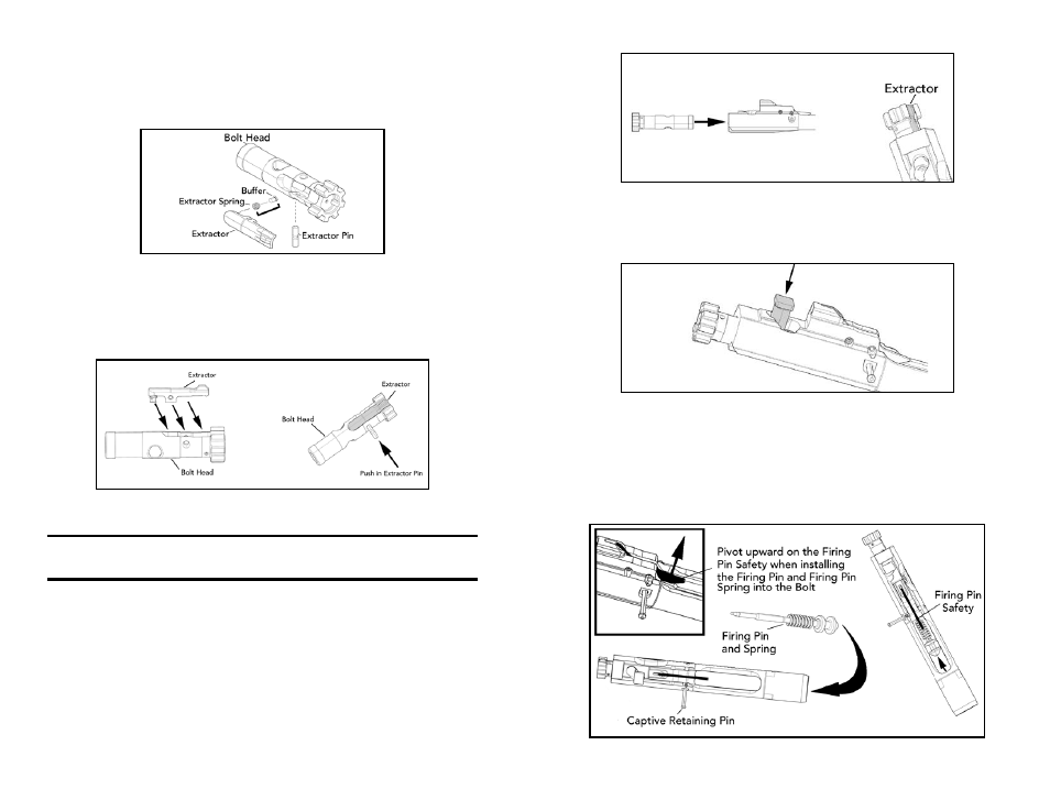
3. Bolt Assembly:
a. Mount the extractor spring and buffer onto the extractor, ensuring that the wider
surface of both the spring and buffer are mounted on the circular mounting surface
on the extractor and that the tapered (narrower) surface faces upwards (Fig. 55).
Fig. 55 – Extractor reassembly
b. Insert the extractor with spring and buffer into the bolt head. Place pressure on the
back of the extractor, line up the mounting surfaces and install the extractor pin.
Ensure the extractor pin is centered in the bolt head before attempting to install the
bolt head into the bolt carrier (Fig 43).
Fig. 56 – Bolt Head reassembly
NOTE: The bolt head on the MR556A1 features a tapered mounting surface for the
cam pin. This feature ensures that the bolt must be properly positioned in the bolt
carrier before attempting to install the cam pin.
c. Slide the bolt head into the bolt carrier until the circular mounting surface for the cam
pin on the bolt heads aligns with the front of the raceway on the bolt head carrier.
Pointed down range, the extractor should be on the right hand side of the bolt carrier
and ejector should be on the left (Fig. 57).
Fig. 57 – Bolt Carrier reassembly
d. Insert the cam pin into the shaft of the bolt carrier, ensuring that the hole for the firing
pin on the cam pin is aligned with the firing pin tunnels on both the bolt head and
bolt carrier (Fig. 58).
Fig. 58 – Bolt Carrier reassembly
e. Ensure that the captive firing pin retaining pin is drifted completely out to the left
hand side of the bolt carrier. Insert the firing pin spring onto the firing pin, pivot
upwards on the spring loaded firing pin safety, and insert the firing pin and spring
into the bolt carrier’s firing pin tunnel until the firing pin reaches its limit of forward
travel (Fig. 59)
Fig. 59 – Installing the Firing Pin