Haltech HT010613 User Manual
Page 4
Overview
The Haltech Digital Reluctor Adaptor 2 converts the analog signal from a reluctor
sensor into a digital signal which the engine computer uses to determine the
position of the crankshaft and/or camshaft.
The Digital Reluctor Adaptor has two identical channels, each with a "+" and "-"
input, and one output. The two inputs of each channel are connected to each
wire of the two-wire reluctor sensor, regardless of whether it is connected to the
vehicle's existing engine computer or not.
The output of each channel is connected to an input of the ECU.
There are many kinds of reluctor sensors, so each channel of the digital reluctor
adaptor can be adjusted to best match the signal from the reluctor sensor
connected to it.
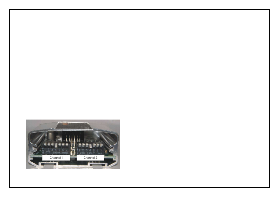
There are two blocks of small switches behind the blank end cover plate. One
block for each channel. Only ONE of the first six switches in each block should
be "ON" (down).
Switch 1 (left-hand end) has lowest sensitivity, up to Switch 6 which has highest
sensitivity. A lower sensitivity setting is more resistant to interference from noise
sources such as ignition coils. It is recommended to use the lowest sensitivity
setting while still allowing the Digital Reluctor Adaptor to detect a full signal.
Factory sensitivity setting will be “4”.
Figure 1 – Haltech Digital Reluctor Adaptor 2 with end plate removed
Installation Guide
Connect the Pink wire to a +12V Switched Supply
Connect the Black wire to a Chassis Ground
Connect Channel 1 and Channel 2 “+” and “-” Inputs to your reluctor sensors
Connect the corresponding Channel 1 / Channel 2 outputs to the ECU input
Notes
•
Channel 1 or 2 paired input wires can be connected to either side of
the reluctor sensor wires as long as the correct trigger edge is selected
within the ECU Manager Software
•
If neither reluctor wire is grounded at the sensor, then ground one of them.
It does not matter which one.
•
If there is a severe noise problem, then use shielded wire with the shield
connected to ground
Setup Guide
As a guide, reluctor sensors (both Trigger/crank and Home/camshaft) on most
engines will work properly with Switch 4 "ON". However some engines require
different settings. Here's a short list:
Toyota 20v 4AGE engines need Switch 4 "ON" for the Trigger (crankshaft)
sensor, and Switch 3 "ON" for the Home (camshaft) sensor.
Ford AU V8s need Switch 4 "ON" for the Trigger (crankshaft) sensor, and Switch
6 "ON" for the Home (camshaft) sensor
.
Ford Cosworth Sierra Switch 3 “ON for the Trigger (crankshaft) sensor, and
Switch 4 “ON” for the Home (camshaft) sensor.
Some Subarus need Switch 3 "ON" for both the Trigger (crankshaft) sensor and
the Home (camshaft) sensor.
Some MSD distributors have high output and need to have Switch 2 or Switch 1
"ON".
As a guide, you can start out by turning Switch 3 "ON" and see if the engine will
start. If it won't start, turn Switch 3 "OFF" and turn Switch 4 "ON" to increase
sensitivity, and see if it will start then. If the engine computer is still not getting an
output from the Digital Reluctor Adaptor channel during cranking, repeat the
procedure with Switch 5 and even Switch 6 if necessary.