Haltech HT051202 User Manual
Page 7
Appendix
Series 6 Engine Harness Conversion
Crank Angle Sensor
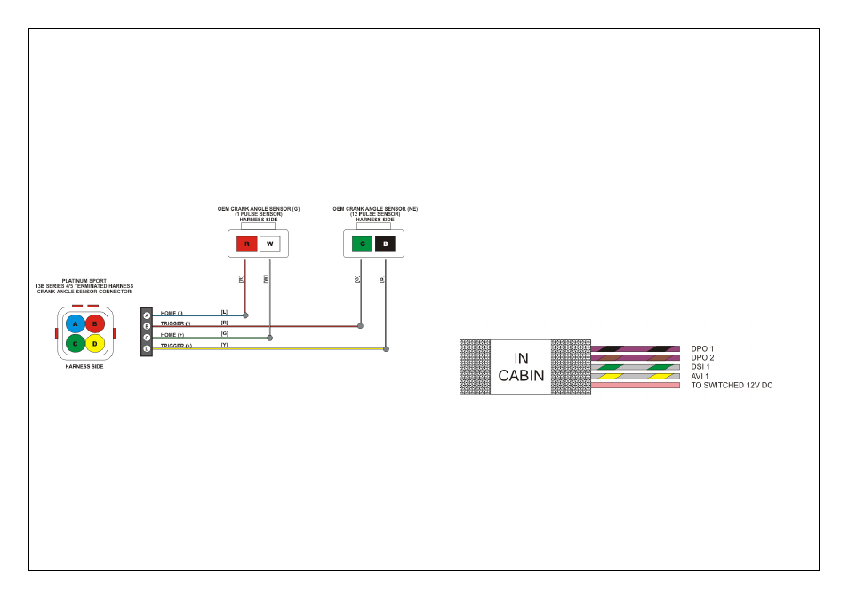
To Convert the Haltech Terminated harness to be used with a Series 6 engines
the Crank angle sensor connection must split into two sensor connectors.
Cut your existing connectors off your original harness and solder them to the
Haltech terminated harness as shown below
Figure 12 – Series 6 Crank Angle Sensor Wiring
•
Analogue Voltage Input (GY/Y)
Analogue Voltage Inputs accept variable voltage inputs from 0V to 5V.
These inputs can also accept switch inputs that change between two different voltage
levels. The on voltage and off voltage define what the thresholds are between the on
and off states. The voltage can be viewed as a channel in the ECU Manager software
to determine thresholds for a switched input.
This input can be programmed within the ECU Manager Software to read inputs
such as:
•
02 Sensors
•
Pressure Sensors
•
Temperature Sensors
•
Various Switches
For a full list of input options and explanations please go to the help within the
ECU Manager Software.
•
Switched +12V DC Input ( P )
This input must be connected to a +12VDC Switched Ignition Source.
This is required to turn on the Haltech ECU and all the Relays contained
within the terminated harness.
Figure 2 - In Cabin Wire Harness