Get the model ready to fly, Check the control directions, Apply the decals – Great Planes Mini Super Sportster EP ARF - GPMA1156 User Manual
Page 16
❏
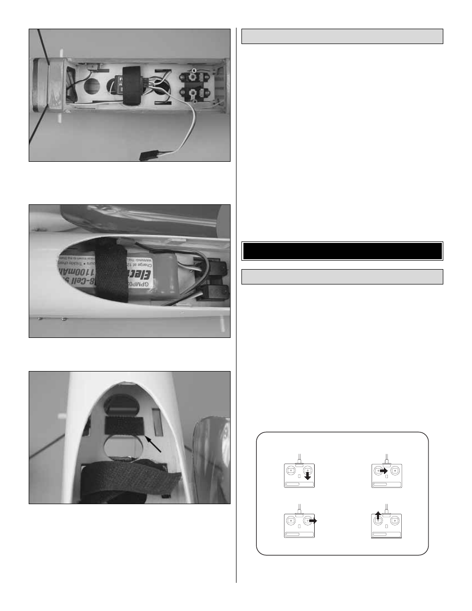
2. Insert the hook-and-loop strap through the middle slots
from the bottom of the battery tray. Position the strap over
the receiver to help hold it in place.
❏
3. Insert the motor battery in the cockpit and trim the
hook-and-loop strap so that it holds the battery secure.
❏
4. To prevent the battery from sliding around, glue a piece
of hook-and-loop material to the battery tray forward of the
strap. Once the plane has been balanced and the battery
location has been determined, glue a corresponding piece
of hook-and-loop material to the battery.
1. Use scissors or a sharp hobby knife to cut the decals from
the sheet.
2. Be certain the model is clean and free from oily fingerprints
and dust. Prepare a dishpan or small bucket with a mixture of
liquid dish soap and warm water–about one teaspoon of
soap per gallon of water. Submerse the decal in the soap and
water and peel off the paper backing. Note: Even though the
decals have a “sticky-back” and are not the water transfer
type, submersing them in soap and water allows accurate
positioning and reduces air bubbles underneath.
3. Position decal on the model where desired. Holding the
decal down, use a paper towel to wipe most of the water away.
4. Use a piece of soft balsa or something similar to
squeegee remaining water from under the decal. Apply the
rest of the decals the same way.
Warning: Once the motor battery is connected to the
electronic speed control, stay clear of the propeller.
❏
1. Switch on the transmitter and connect the motor
battery to the electronic speed control. Move the throttle
stick down to the off position. Switch on the speed control
and center the trims. If necessary, remove the servo arms
from the servos and reposition them so they are centered.
Reinstall the screws that hold on the servo arms.
❏
2. With the transmitter and receiver still on, check all the
control surfaces to see if they are centered. If necessary,
adjust the pushrods at the pushrod connectors to center the
control surfaces.
❏
3. Make certain that the control surfaces respond in the
correct direction as shown in the diagram. If any of the
FULL THROTTLE
RUDDER MOVES RIGHT
LEFT AILERON MOVES DOWN
RIGHT AILERON MOVES UP
ELEVATOR MOVES UP
4-CHANNEL
TRANSMITTER
(STANDARD MODE 2)
4-CHANNEL RADIO SETUP
TRANSMITTER
4-CHANNEL
TRANSMITTER
4-CHANNEL
TRANSMITTER
4-CHANNEL
Check the Control Directions
GET THE MODEL READY TO FLY
Apply the Decals
16