Assemble the fuel tank – Great Planes Easy Sport 40 ARF - GPMA1035 User Manual
Page 9
fit of the outer pushrod tubes to the pushrod exits. If the fit
is too tight, trim the opening slightly with a hobby knife to
allow the pushrod to fit without binding.
❏
3. Roughen the outside of the outer pushrod tubes
using 220-grit sandpaper.
❏
4. Insert the 36" threaded wire rods through the
pushrod tube openings into the fuselage from the rear and
guide them through former #4. Do not allow the pushrods to
cross each other inside the fuselage. If the pushrods are
crossed during the installation, the nose gear will operate in
the opposite direction of the rudder, making ground handling
of the aircraft rather difficult. Slide the outer pushrod tubes
into place from the inside using the threaded rods as guides.
Leave approximately 1" of the outer pushrod tube in front of
former #4. Apply thick CA to the points where the outer tubes
contact former #4 and at the exits.
❏
5. Trim one of the remaining pushrod tubes to 12". After
roughening the tube with 220-grit sand paper, install the
tube into the upper right hole in the firewall. This will be
used for the throttle pushrod. Leave about 1/4" of the tube
exposed in front of the firewall. Glue the pushrod tube to
both sides of the firewall using medium CA.
❏
6. Trim the other remaining outer pushrod to 13-1/2" for
use as the nose wheel pushrod tube. After roughening the
tube with 220-grit sand paper, install the tube into the lower
left hole in the firewall. This tube should be installed flush
with the front of the firewall. Glue the pushrod tube in place
from the back of the firewall using medium CA.
❏
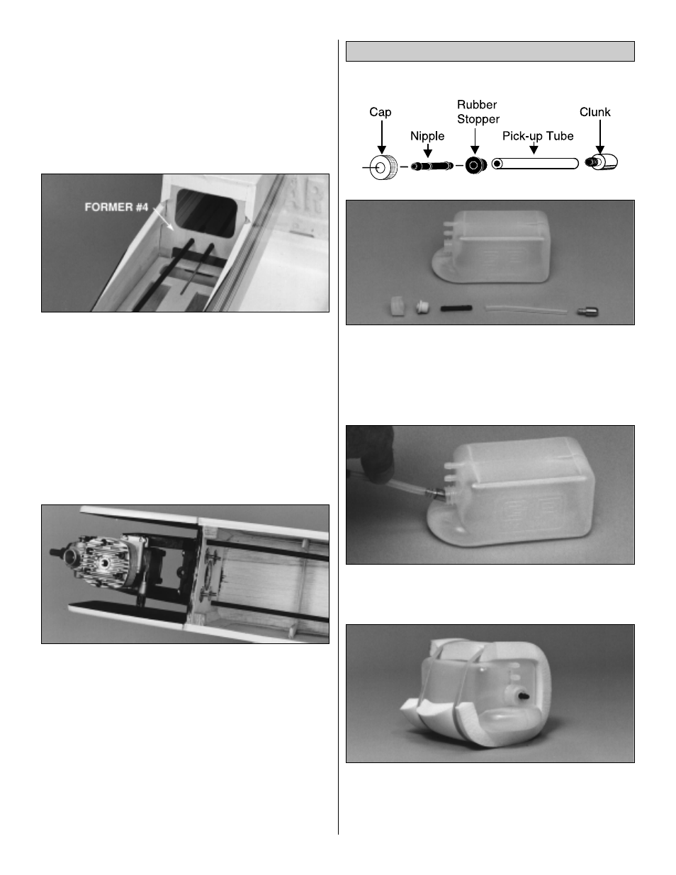
1. Push the straight nipple through the rubber
stopper until the ridge (1/4" from one end) contacts the
outside face of the stopper. Cut the pick-up tube to 2-7/8".
Push one end of the pick-up tube all the way onto the
clunk and the other end all the way onto the nipple.
❏
2. Insert the pick-up tube assembly into the tank, then
thread the cap over the stopper, tightening it securely.
❏
3. Wrap the 3-1/2" x 7-7/8" x 1/2" sheet of foam rubber
around the tank as shown in the photo. Secure it into
position with a couple of rubber bands. The reason for the
open area on the side of the tank is to allow clearance for
the throttle pushrod tube.
Assemble the Fuel Tank
9