Great Planes BL-8 Brushless ESC - GPMM2070 User Manual
Page 2
2
on Futaba
®
, the blue wire on the newer Airtronics “Z” connector, the
yellow wire on the Hitec “S” connector, or the orange wire on the JR
connector. WARNING: This connector is NOT directly compatible with
the old Airtronics connector style. Use an Airtronics Servo Adapter to
connect this ESC to the older style Airtronics radios.
DISABLING THE BEC CIRCUIT
If using more than 10 NiCd/NiMH or 3 Li-Po cells, it will be necessary
to disable the speed control’s BEC circuit and connect a separate
battery to power the receiver and servos. Failure to do so will
permanently damage the BEC circuit. To disable the BEC circuit:
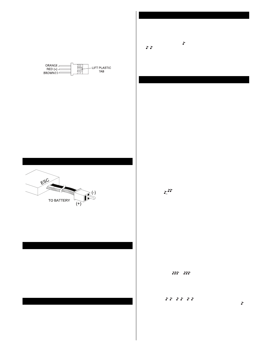
A. The red wire and its terminal should be removed from the plastic
shell. To do this use a small flat bladed screwdriver to slightly,
carefully raise the plastic tab holding the metal pin. Carefully pull
the red wire out of the receiver plug. Or, cut a small section of the
red wire out completely with wire cutters.
B. Always make sure to cover the bare terminal or cut wire with electrical
tape or shrink tubing to avoid an unwanted short circuit condition.
C. Connect the ESC’s receiver connector to the receiver’s throttle
channel (see your radio’s instruction manual for details).
A separate battery will then need to be connected to the receiver.
When the BEC circuit is disabled, it will be important to remember not
to exceed the ESC’s maximum rated current!
WARNING: NEVER ALLOW THE BARE RED (+) AND BLACK (-)
WIRES TO TOUCH ON ANY RECEIVER OR ESC,
AS
PERMANENT DAMAGE WILL RESULT TO BOTH ITEMS AND
VOID ALL WARRANTIES!
A polarized micro
connector is pre-
installed for
connecting the ESC
to an external
battery pack. It’s a
good idea for the
length of wire
between the battery
and ESC to be no
longer than 6
inches. IMPORTANT! Make sure the polarity of the battery’s
wires/connector matches the polarity of the wires/connector on
the ESC, with the battery and ESC’s red (+) wires connected and
the black (-) wires connected together. NEVER allow the bare red
(+) and black (-) wires to touch as permanent damage will result
to both items and void all warranties.
The BL-8 has three output leads. Female 2mm bullet connectors are
pre-installed on each lead. These connections are not polarized, so
there is no need to match the color of the ESC’s wires to the motor’s
wires. Once connected to the motor, make sure all connections are
insulated electrically. Failure to do so could result in permanent damage
to the motor/ESC if the output leads touch each other while power is
applied to the ESC, thus voiding all warranties. If the motor operates in
the opposite direction desired, switch any two of the motor wires to
reverse the motor’s rotation, or adjust the “reverse rotation” setting in the
BL-8’s programming (see page 3).
Proper adjustment of the transmitter’s controls is critical for proper
operation of the ESC. The transmitter’s throttle channel adjustments
should be set as follows:
A. Set the throttle travel adjustment (ATV, EPA or ATL) to maximum
(+/- 100% or the greatest value available).
B. Set the throttle trim and sub-trim to neutral, or zero.
C. For most radio types (including Futaba, Hitec and others) set the
throttle channel’s reversing option to “reverse.”
The BL-8’s normal start-up procedure is very simple, as follows:
A. Turn the transmitter’s power switch to “ON.”
B. Move the Tx throttle stick to MINIMUM position.
C. Connect the battery to the ESC.
D. You will hear one tone
“
”
if the brake is set to “ON,” or two tones
“
”
to indicate the brake is set to “OFF.”
E. If the brake setting is O.K. and no other programming adjustments
are needed, skip directly to Step 8 and get ready to fly. If you do
wish to change the brake setting or any other programmable
feature, disconnect the battery and go to Step 7 below.
The BL-8 has seven programmable features, and will automatically
step through each feature in order as shown below. It is not
necessary to wait for the ESC to step through all seven
programmable features unless you wish to change the setting of the
last feature. Each programmable feature has its own distinguishing
series of audible tones. Selecting/changing features is accomplished
by moving the Tx’s throttle stick in conjunction with certain tones that
are emitted by the ESC. Anytime a programmable feature has been
set the ESC will memorize the setting until it’s changed again
manually. Before entering the programming mode, remove the
propeller from the motor and make sure the battery is disconnected
from the ESC. It’s a good idea to read through all steps below
BEFORE attempting to program your ESC.
IMPORTANT!!
It’s critical to remember that only ONE
programmable feature can be adjusted at a time. To change more
than one programmable feature, after changing the first feature you
must disconnect the battery from the ESC, reconnect the battery,
then re-start the programming mode below to change the next
programmable feature. It will be necessary to repeat this process for
each programming change that you wish to make.
A. Turn the transmitter’s power switch to “ON.”
B. Move the Tx’s throttle stick to FULL throttle.
C. Connect the battery to the ESC. After a 5 second delay two tones
will sound “
” to indicate the programming mode has been
entered. The ESC will automatically begin scrolling through all of
the programmable features in this order: brake > battery type >
reverse rotation > soft start > low voltage indication > timing >
switching frequency > restore defaults > RPM control. Follow the
points below to change any of these features.
D. BRAKE: To change the brake setting, simply pull the throttle stick
to minimum within five seconds of hearing the programming tones
noted in step C above. This will change the state of the brake
setting - if the brake was on this will turn it off, and vice-versa. You
can determine which setting is active by listening to the arming
tone. One tone indicates that the brake is enabled, and two tones
indicates that the brake is disabled. Skip to Step 8 if you do not
wish to make any other programming changes. To CHANGE
ANOTHER programmable feature disconnect the battery from the
ESC and return to Step B above.
E. BATTERY TYPE: The ESC will automatically sound three
different series of tones to indicate the three battery type settings
as shown below. If you do NOT wish to change the battery setting
wait after the “
” tones sound and the ESC will
automatically skip to the reverse rotation feature below. To
CHANGE the battery type, move the throttle stick to minimum
when you hear the tones that match the setting you wish to have.
For example, to set for a “2-cell Li-Po” battery wait until the tones
for NiCd batteries have ended, then when 2 short tones sound
repeatedly “
”
move the Tx throttle stick to
minimum position. The ESC will then sound a single tone
“
”
to
indicate the new setting was accepted, and the ESC is now armed
and ready for operation. Skip to Step 8 if you do not wish to make
any other programming changes. To CHANGE ANOTHER
programmable feature disconnect the battery from the ESC and
return to Step B above.
WARNING: Failure to set the proper
battery type will likely result in unwanted operation and/or
damage to your battery.
STEP 7 – PROGRAMMING MODE
STEP 6 – NORMAL START UP
STEP 5 – TRANSMITTER ADJUSTMENTS
STEP 4 – MOTOR CONNECTIONS
STEP 3 – BATTERY CONNECTION