Mount the tail gear, Mount the servos & hook up the controls – Great Planes Giant Super Sportster ARF - GPMA1044 User Manual
Page 13
cut and peel off the covering, and then use 30-minute epoxy
to glue the fin into position. Use a builder’s triangle and if
necessary, pull the top of the fin over to one side or the other
of the stab.
❏
10. After all the epoxy has hardened, join the elevators to
the stab and the rudder to the fin with the CA hinges and thin
CA. Don’t forget to use T-pins to keep the hinges centered
as you fit the elevators and rudder.
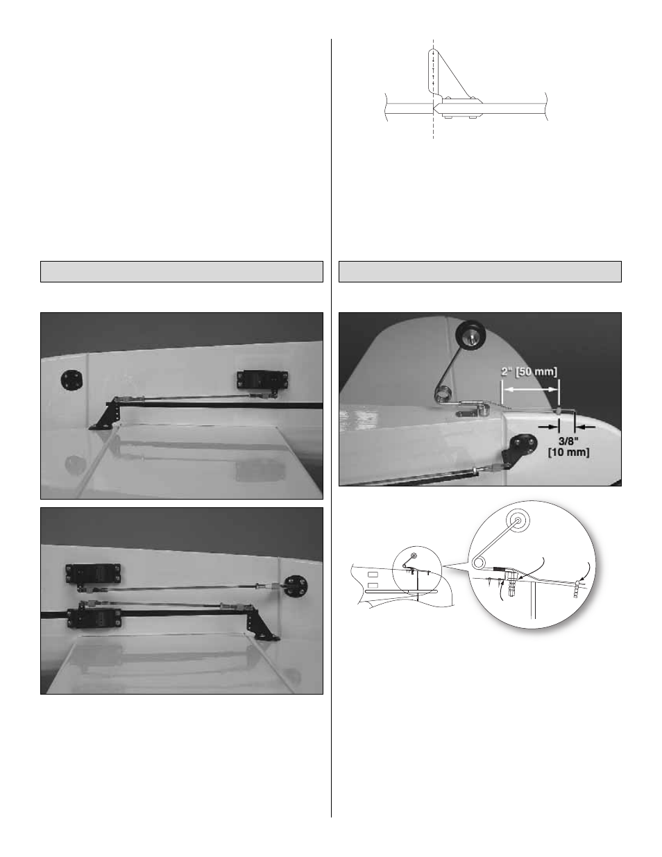
Refer to these photos while mounting the servos.
❏
1. Connect a 24" [610 mm] servo extension to both elevator
servos and the rudder servo. The same as with the aileron
servo extensions, secure the connections with the heat shrink
tubing provided with this kit.
❏
2. Guide the servo wires through the fuselage up into the
radio compartment and mount the servos using the screws
that came with them (the screw holes should have been
previously drilled and hardened).
❏
3. Make the pushrods and connect the servos to the control
surfaces using the same hardware that was used for the
ailerons-except use 4-40 x 3/4" [19 mm] Phillips screws and
the mounting plates on the other side of the control surfaces
for mounting the horns. When mounting the horns, locate the
clevis holes over the pivot point and drill 1/8" [3.2 mm] holes for
the screws through the control surfaces.
Refer to the photo and the sketch to mount the tail gear.
❏
1. Cut the covering from the 1/4" [6 mm] hole in the bottom
of the fuselage for the nylon tail gear bearing. Glue the
bearing in place with CA. Use care not to get any glue into
the hole in the bearing.
❏
2. Mount the tail wheel to the tail gear wire with the small
wheel collar and the set screw and mount the tail gear to the
fuselage with the rest of the hardware shown. Use a 1/16"
[1.6 mm] drill to drill the holes in the bottom of the fuselage
for the screws. Don’t forget to install, then remove, the screws
and harden the holes with a few drops of thin CA. Drill a 5/32"
[4 mm] hole into the bottom of the rudder for the steering pin.
Glue the pin in place with CA. Cut off the excess wire.
TAIL GEAR
BEARING
S
TEERING
PO
S
T
ALUMINUM
BRACKET
Mount the Tail Gear
ALIGN THE PU
S
HROD HOLE
S
WITH THE PIVOT POINT.
Mount the Servos & Hook Up the Controls
1
3