Cutter - drive belt collector - drive belts – Countax A50 User Manual
Page 13
Page 16
Page 13
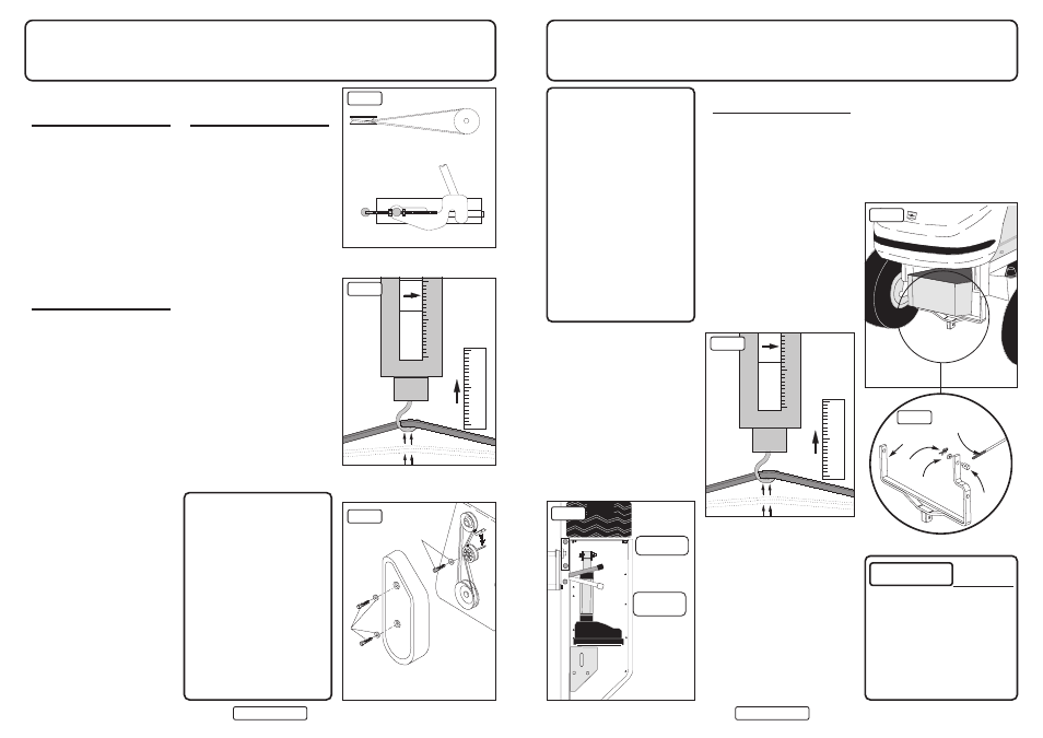
Cutter - Drive Belt
Collector - Drive Belts
Before carrying out tests or adjustments
(the problem may be simpler) – first
CHECK the following points:
1. Is the Engine to Cutter Drive Belt
slipping? Check that the Drive Belt
Tension Lever (fig 1) under the left
running board is in the rear (tensioned)
position. If not, rectify – this is the
most likely cause.
2. Has debris collected in the Cutter Deck
Pulley Housing (Page 9)? If so remove
the cover and remove the
obstruction.
ENGINE TO CUTTER DRIVE
BELT TENSION
The correct tension of the Cutter Drive
Belt (Engine to Deck) is critical. If
incorrectly set it can lead to engine
damage.
To check the tension, follow this
procedure:
1. Put the Deck in a middle cutting height
position (5 on the decal).
2. Select the midway position on the Belt
between the front (Electric Clutch)
pulley and rear (Cutter Deck) pulley
and using, a spring balance; apply a
2Kg (4 to 5lbs) pull (fig 2).
3. Using a ruler or tape, measure the
deflection achieved which must be
13mm (1/2"). If more the belt tension
must be increased, if less decreased.
To correct the tension, follow this
procedure:
1. Release the tension on the belt by
pulling the Belt Tension Lever forward
(see fig 1).
2. Taking care not to burn yourself on a
hot exhaust, locate the Trunnion at the
end of the Belt Tension Rod – lift the
bonnet and look to the front (nearside)
close to the exhaust (see fig 3).
3. Remove the spring clip and washer
holding the Trunnion in place on the
Deck Tension Cradle (fig 3a) and
release the Trunnion so it can be
turned.
4. Both the Trunnion and the Belt Tension
Specified Belts and Blades
Engine/Deck Belt - B57 Dayco Super II -
Pt No. 22940100
Deck Internal Drive (Mulcher) - BB112
Pt No. 228000900
(Rear Discharge) - Dayco Super II BB155
Pt No. 22950200
Mulcher Blades x3 Pt No. - 16938100
IBS RH Blade Pt No. 169381300
IBS LH Blade Pt No. 169381400
IBS Front Blade Pt No. 1692000
PGC A49 Drive Belt Pt No. 22923400
PTO Drive Belt - Dayco Super II A92 -
Pt No. 22950100
Transmission Drive Belts - A91 Dayco
Super II - Pt No. 228001500
N.B. Only use specified Belts and Blades
- Never accept a substitute!
Rod are threaded. You increase Belt
tension by winding the Trunnion
towards the end of the Rod and reduce
tension by winding in the reverse
direction.
5. Having made the adjustment re-locate
and secure the Trunnion, re-tension the
Belt with the Belt Tensioner Lever –
then re-check the Belt tension.
ON NO ACCOUNT MUST THE
TRACTOR BE RUN WITH THE
ENGINE TO CUTTER DRIVE BELT
OVER-TENSIONED AS IT WILL
DAMAGE THE ENGINE. As any such
damage will NOT be covered by
warranty you may prefer that your
dealer sets the tension.
Kg
cm
fig 1
fig 2
fig 3
View from underside
Trunnion
Deck Tension
Washer
Cradle
Spring Clip
Deck Tension Rod
WARNING
REPLACING AND
TENSIONING PTO DRIVE
BELT CONNECTION
It is important that the belt from PTO to
collector (Part No. 22923400) is crossed
over in the correct direction (fig 1) before
being fitted over the collector pulley. The
easiest way to do this is to place the belt
on the PTO pulley and then stand behind
the Tractor holding the belt with two
hands. Turn the right hand above the left
and fit the belt on to the collector pulley.
To check that you have this right - start
your Tractor and engage the PTO lever
and check that the brush is revolving
against the forward direction of the
Tractor (see page 15 fig 1).
CORRECT BELT TENSION
To check tension:
1. Lower the collector to the operating
position and check the tension using a
spring balance and a ruler.
2. Select a place on the belt midway
between the PTO pulley and the
collector pulley.
3. Pull and measure the deflection using a
ruler (fig 2). It should be 19mm at 2kgs
(4-5lbs).
If the tension needs to be adjusted - first:
1. Relocate the Collector from the
Tractor.
2. Locate the adjustment holes on the
Locking Arms. These holes take the
nuts and bolts on which the Locking
Arm hinges.
3. To increase tension on the belt undo
each nut and bolt and relocate them
one or more holes forward (towards
the Tractor). To slacken move the bolts
back. Ideally the bolts should be in the
same hole on each Locking Arm,
however fine adjustment to get the
right tension may only permit you to
move one bolt - this is OK but there
should not be more than one hole
difference from side to side.
4. Replace the Collector on the Tractor
and re-check the belt tension.
CHECKING, TENSIONING
AND REPLACING SIDE
DRIVE BELT (fig 3)
1. First remove Collector from the
Tractor (page 14).
2. To remove the plastic cover, remove
the two nuts and bolts (A) using a 1/2”
spanner and socket.
3. Using a 1/2” spanner and socket,
slacken the nut and bolt (B) holding
the tension pulley and slide the pulley
out of the way.
4. Remove the belt and fit the Countax
replacement (Dayco Super II A38 Part
No. 22950300)
5. Tension the belt by sliding back and
securing the belt tensioner. The tension
is not critical but the belt must not be
too tight. The ideal is 13mm (1/2”)
deflection at 2Kgs (4/5lbs) pull -
use a spring balance and ruler or tape
to check.
6. Make sure that the rectangular cover
plate fits over the adjustment slot -
failure to do this will allow cuttings
and grit to accumulate and damage the
pulleys and belt assembly.
7.Replace the plastic cover.
Kg
cm
A
B
PLEASE NOTE:
The information contained in
the following pages is given
on the understanding that
Countax accepts no
responsibility for work
carried out by a customer or
for any damage thus caused,
whether or not the service
instructions have been
misunderstood. To be
absolutely sure that your
warranty terms are not
breached, service work
should only be carried out by
a Countax dealer.
fig 3a
19mm deflection 2kgs push or pull
To Tighten
To Slacken
fig 1
fig 2
fig 3
Cutter Belt
De-Tensioned
Cutter Belt
Tensioned